Mobile device clamp holder with damped release mechanism

a technology of release mechanism and clamp holder, which is applied in the direction of machine supports, transportation and packaging, and other domestic objects, etc., can solve the problems of difficult operation, unfavorable use, and the simplest possible handling of the clamp holder

Active Publication Date: 2009-06-02
III HLDG 3
View PDF10 Cites 36 Cited by
  • Summary
  • Abstract
  • Description
  • Claims
  • Application Information

AI Technical Summary

Benefits of technology

[0007]The object of the present invention is therefore to provide an improved holder with which the disadvantages mentioned above are eliminated.
[0011]an elastic element connected at least to the first clamping jaw, its spring force being effective in forcing the first clamping jaw away from the second clamping jaw;
[0016]The lifetime of the holder is increased by such a holder which eliminates or at least reduces the noise nuisance when the holding mechanism is released while at the same time giving the user an impression of higher quality.
[0023]pad elements mounted on the insides of the clamping jaws to protect a mobile electronic device held between the clamping jaws.This prevents scratches, etc., on the housing of the device, and the pads may also serve to improve the holding of the device, e.g., by using pads having elastic properties and a slip-proof surface.
[0025]at least one holding element which is mounted on the base element to prevent a mobile electronic device being held thereby from falling out.Such a holding element also serves as a stop for the device before the clamping jaws are closed, so that no hands are needed to hold the device.
[0028]In one exemplary embodiment, the damper element(s) is (are) in frictional engagement with the entraining element over at least a portion of the displacement path. This allows additional damping and retardation of the movement of the clamping jaws to be achieved, at least in the vicinity of the extreme position, which then corresponds to the maximally opened clamping jaws.

Problems solved by technology

Secondly, the simplest possible handling of the holder is required.
Although this approach is easy to implement and works satisfactorily with regard to securing the device, operation is difficult.
The necessarily forceful impact against the stop causes unwanted noise, and there is a risk of damage to the stop in the long run, so it no longer functions properly (e.g., breaking off).
The durability of the entire holder, which is made of plastic, for example, may be impaired due to heavy vibrations (causing cracks, etc.).
Sudden impact against the stop when the clamping jaws spring open is therefore undesirable, because this not only shortens the lifetime of the holder but the loud noise also gives the user the impression of low-quality workmanship.

Method used


Image

  • Mobile device clamp holder with damped release mechanism
  • Mobile device clamp holder with damped release mechanism
  • Mobile device clamp holder with damped release mechanism

Examples


Embodiment Construction

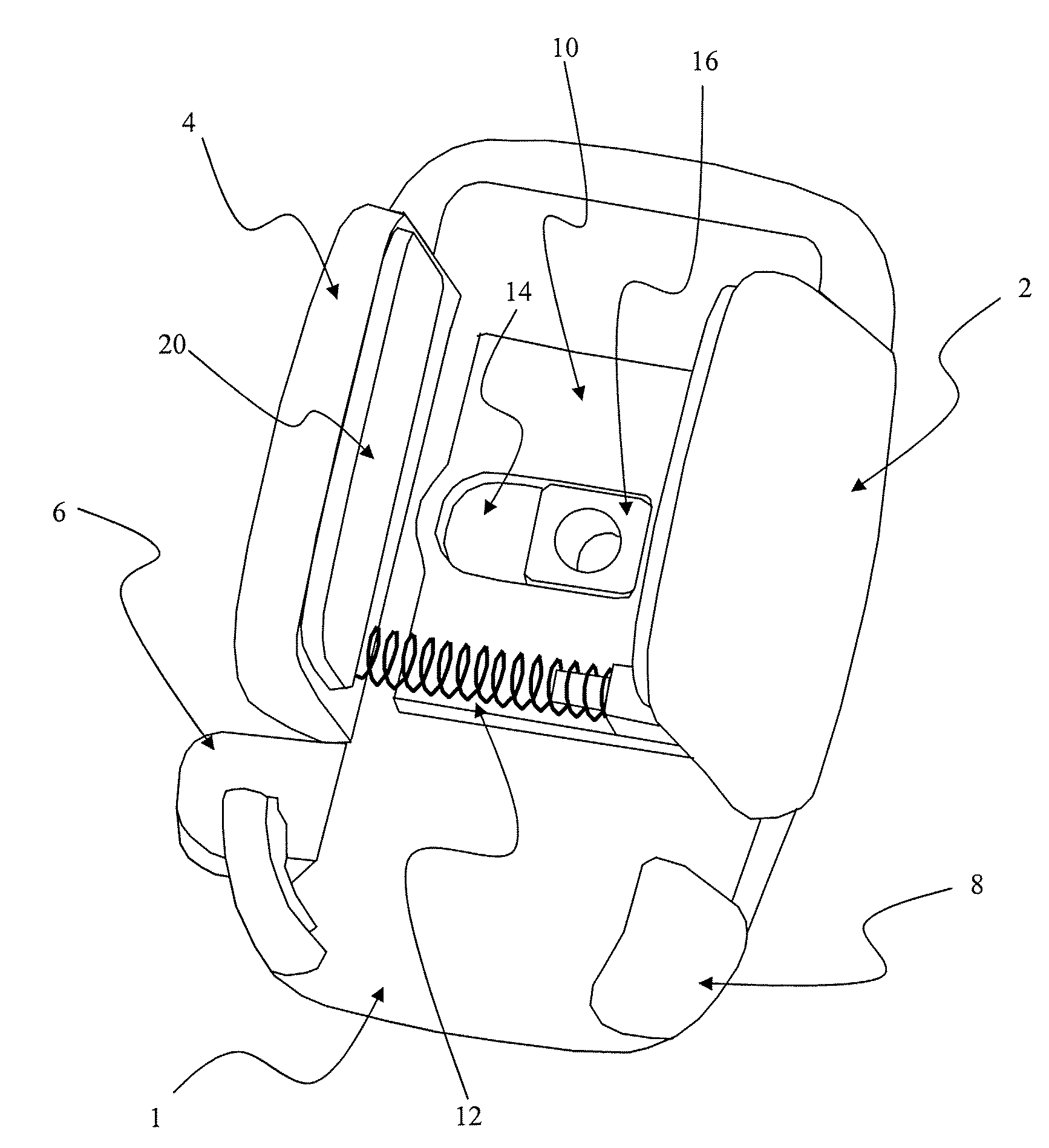
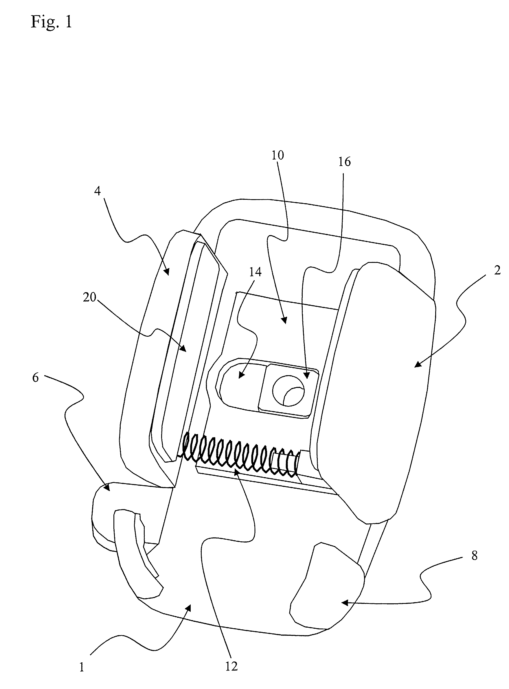
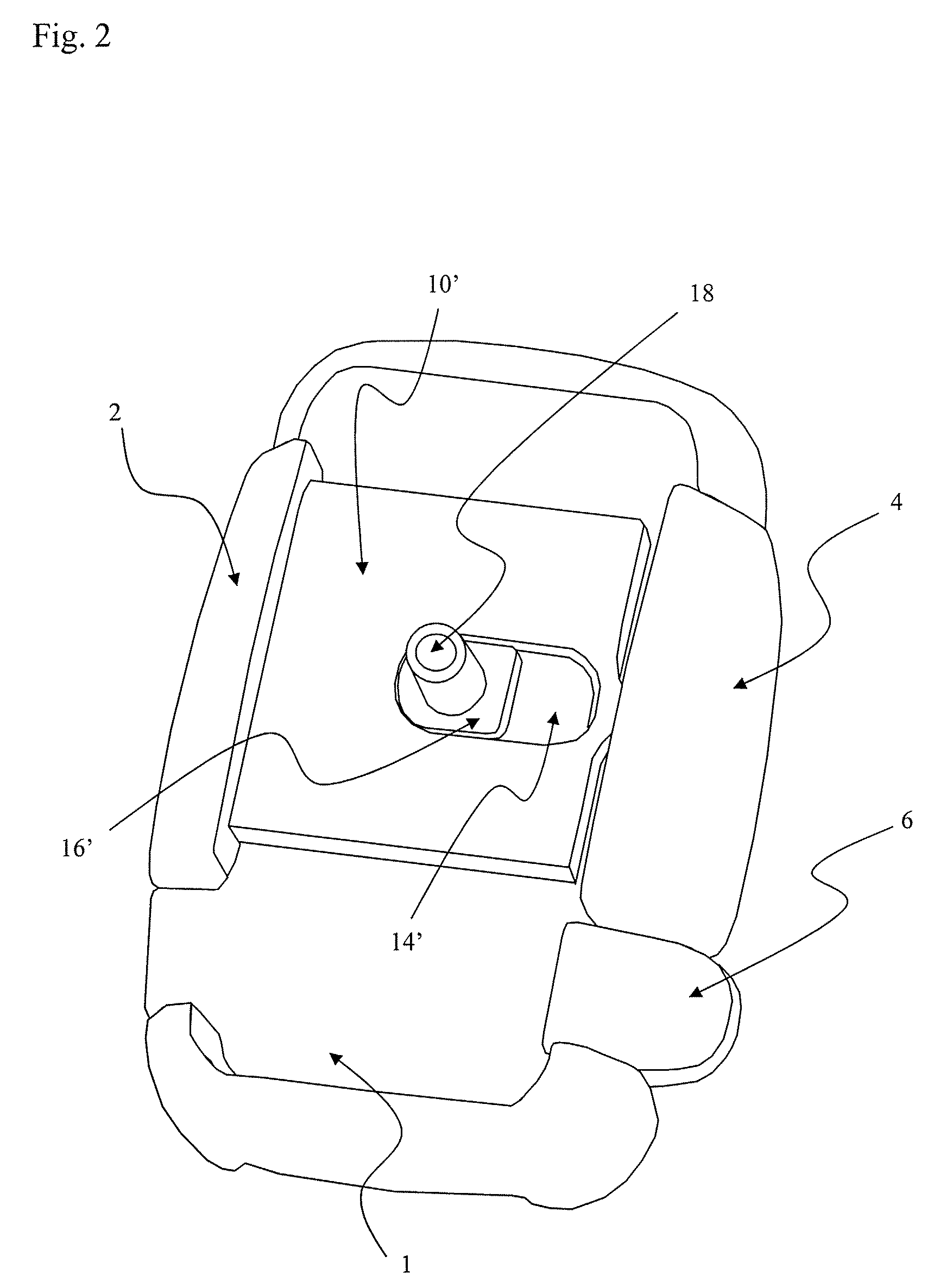
[0031]FIG. 1 shows an exemplary embodiment of the holder of the present invention in a view from the front. Clamping jaws 2, 4 are mounted on a housing or a base plate. The clamping jaws 2, 4 are movably mounted so that they can secure a device (not shown) that is placed in the holder, i.e., they are movable horizontally toward and away from the device. Pads 20 are preferably provided on the clamping jaws 2, 4 to hold the device securely without damaging and / or scratching it.

[0032]The clamping jaws 2, 4 are forced apart by a spring 12 or a corresponding elastic element. A mechanism (not shown) ensures that the clamping jaws 2, 4 are locked, e.g., by means of a suitable catch mechanism, to prevent them from moving apart. A release lever 6 serves to unlock this catch, so that the spring 12 can move the clamping jaws 2, 4 away from the device (not shown) that is placed in the device. Lower holding tongues 8 are provided to form a lower support for a device placed in the device.

[0033]An...


PUM


Abstract

A holder for a mobile electronic device includes first and second clamping jaws, at least the first clamping jaw being displaceable toward the second clamping jaw to clamp the mobile electronic device. The holder also includes a stop element and an entraining element connected to the first clamping jaw, the entraining element being shaped so that it is displaceable with respect to the stop element, namely jointly with the clamping jaw connected to it, in which case at least one extreme position corresponding to the maximum opening of the clamping jaw is defined in the displacement path by the impact of the stop element against the entraining element. The holder includes a damper element, which is mounted on the stop element and damps the stopping of the stop element against the entraining element.

Description

TECHNICAL FIELD[0001]The present invention relates to a holder for mobile electronic devices, in particular cellular telephones, e.g., for installation in motor vehicles.BACKGROUND[0002]Holders for mobile electronic devices are becoming widespread, e.g., for securely holding a cellular telephone in a motor vehicle. Two points are naturally important here. First, the cellular telephone must be restrained securely so that it is held reliably despite the acceleration that occurs when driving a vehicle. Secondly, the simplest possible handling of the holder is required. In other words, the user should be able to easily place the telephone in the holder and remove it from the holder, preferably using only one hand.[0003]There are known holders with which the device is secured by spring-loaded clamping jaws, i.e., the spring force holds the device between the clamping jaws. Although this approach is easy to implement and works satisfactorily with regard to securing the device, operation i...

Claims


Application Information

Patent Timeline
Patent Type & Authority Patents(United States)
IPC IPC(8): A47F5/00B60R11/02H04M1/04H04M1/11
CPCB60R11/0241H04M1/04
Inventor ASANO, MITSUHIROYAMAMOTO, YASUHIROGOLLNITZ, MICHAEL
Owner III HLDG 3
Why Eureka
Try Eureka