Control method of piezoelectric actuator, position control equipment, and disk device

a piezoelectric actuator and control method technology, applied in the direction of maintaining head carrier alignment, device material selection, instruments, etc., can solve the problems of affecting affecting the performance affecting the accuracy of the piezoelectric actuator, so as to reduce the insulation resistance or displacement amount, widen the range of position control, and improve the reliability of the disk device

Inactive Publication Date: 2006-04-20
PANASONIC CORP
View PDF1 Cites 8 Cited by
  • Summary
  • Abstract
  • Description
  • Claims
  • Application Information

AI Technical Summary

Benefits of technology

[0050] This configuration allows, without generating dusts, certain recovery of reduction in insulation resistance or displacement amount that can be caused by position control in the piezoelectric actuator when the position of the head of the disk device is controlled using the piezoelectric actuator. The reliability of the disk device can be therefore largely improved.
[0051] As discussed above, in the control method of the piezoelectric actuator of the present invention, a wide range of voltage can be applied in the position control state of the piezoelectric actuator, and a wider range of position control can be performed. While, in the standby state, reverse low voltage in the direction opposite to the polarization direction is applied, so that reduction over time in insulation resistance can be suppressed. The reverse low voltage applied for suppressing the...

Problems solved by technology

When a piezoelectric element is used as an actuator, conventionally, a piezoelectric film can be electrochemically deformed by an applied voltage, its characteristic degrades, and further a function as a piezoelectric actuator can be damaged.
This degradation is apt to occur especially when the voltage applied for increasing the displacement amount is increased.
In such a case, high voltage is applied to the gap between the electrode films to make high current flow intensively to a part where the electric resistance is decreased by local degradation, and thus a breakdown phenomenon such as occurrence of peeling in the electrode film around the degraded part is caused.
In ...

Method used


Image

  • Control method of piezoelectric actuator, position control equipment, and disk device
  • Control method of piezoelectric actuator, position control equipment, and disk device
  • Control method of piezoelectric actuator, position control equipment, and disk device

Examples


first embodiment

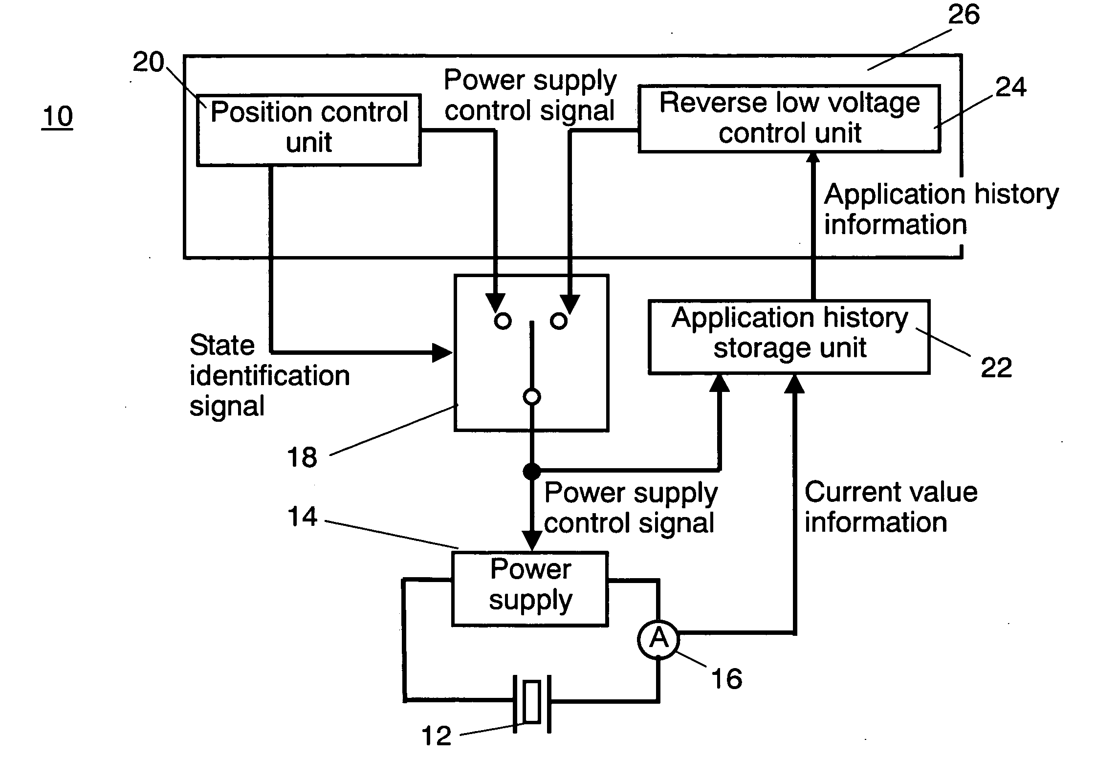
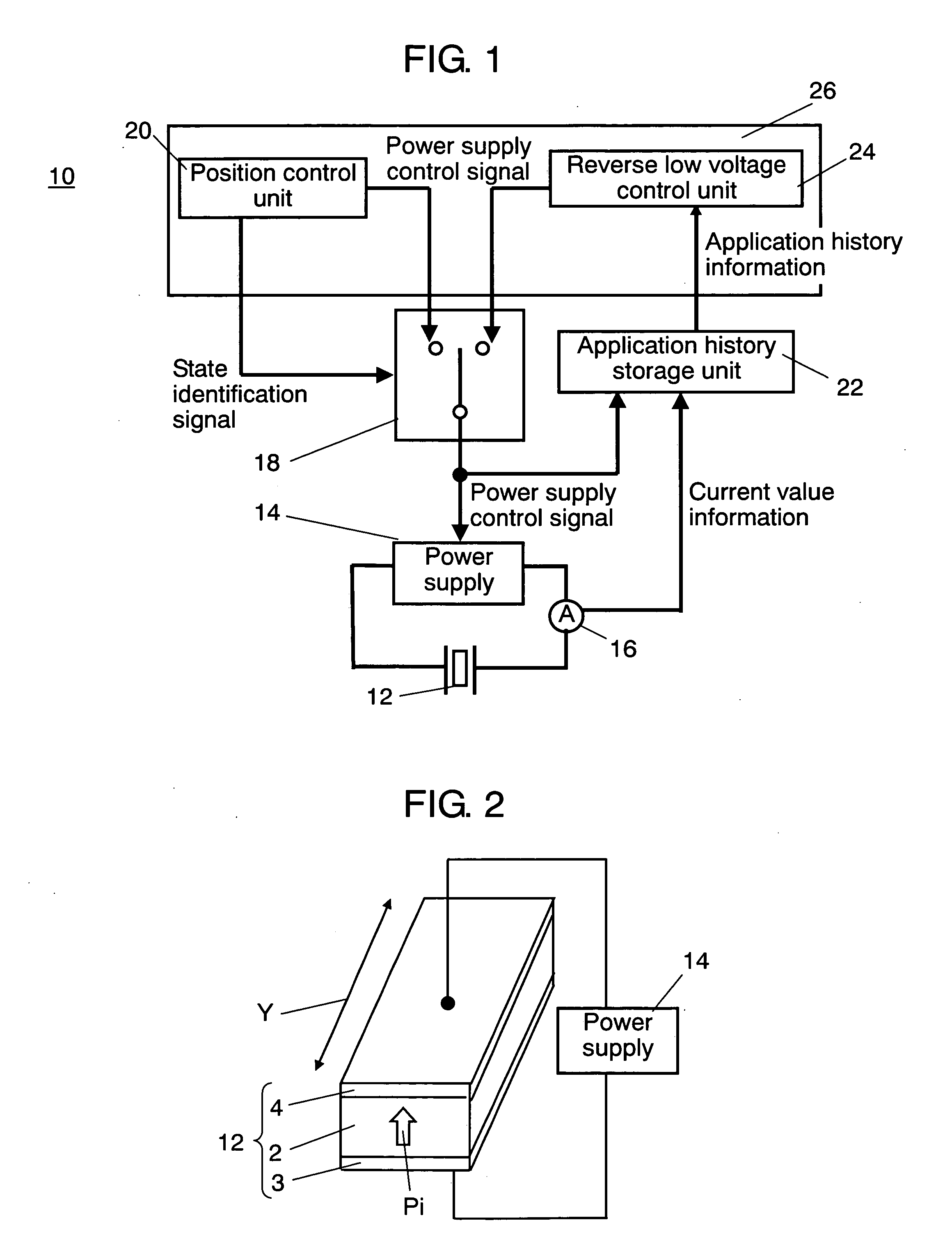
[0062]FIG. 1 is a block diagram of position control equipment 10 in accordance with a first exemplary embodiment of the present invention. A displacement such as expansion and contraction of piezoelectric actuator 12 allows position control of a controlled object (not shown) that is mechanically connected to piezoelectric actuator 12. The displacement amount of piezoelectric actuator 12 is controlled by voltage applied from power supply 14 connected to piezoelectric actuator 12. Ammeter 16 measures current flowing through piezoelectric actuator 12.

[0063] A configuration of position control equipment 10 of the present exemplary embodiment and a control method of the piezoelectric actuator will be described hereinafter.

[0064] The voltage applied from power supply 14 is controlled with a power supply control signal supplied from switch 18. An output source for outputting the power supply control signal depends on whether position control equipment 10 lies in a position control state ...


PUM


Abstract

A position control equipment has a piezoelectric actuator, a power supply for applying voltage to the piezoelectric actuator, a position control unit, and a reverse low voltage control unit. The position control unit identifies a position control state where position control is performed by displacing the piezoelectric actuator and a standby state that does not require the position control, and controls the position. When the position control unit identifies the standby state, the reverse low voltage control unit sets a reverse low voltage that directs oppositely to the polarization direction of the piezoelectric film and is lower than a coercive voltage and a set time during which the reverse low voltage is applied, and transmits a power supply control signal for generating the set reverse low voltage and set time to the power supply. Thus, a large displacement amount is kept and the long lifetime can be realized.

Description

BACKGROUND OF THE INVENTION [0001] 1. Field of the Invention [0002] The present invention relates to a control method of a piezoelectric actuator for displacement control, and more specifically to a control method capable of keeping a large displacement for a long time, and a position control equipment and disk device using this. [0003] 2. Background Art [0004] When a piezoelectric element is used as an actuator, conventionally, a piezoelectric film can be electrochemically deformed by an applied voltage, its characteristic degrades, and further a function as a piezoelectric actuator can be damaged. This degradation is apt to occur especially when the voltage applied for increasing the displacement amount is increased. For suppressing the degradation, various control methods are proposed as the driving method of the piezoelectric actuator. [0005] As the control method of the piezoelectric actuator, Japanese Patent Unexamined Publication No. 2002-288954 discloses a method of restrict...

Claims


Application Information

Patent Timeline
IPC IPC(8): H01L41/09G11B21/10H01L41/18H01L41/187H01L41/316H01L41/318H01L41/39H02N2/00
CPCG11B5/5552G11B5/596H01L41/042H02N2/0075H10N30/802
Inventor KITA, HIROYUKI
Owner PANASONIC CORP
Why Eureka
Try Eureka