
Fuel-air separation structure improvement for engine blow-by of vehicles

a technology for separating structure and engine, which is applied in the direction of machines/engines, combustion air/fuel air treatment, mechanical equipment, etc., can solve the problems of excessive oil discharge, increased blow-by, and large jolts, so as to simplify the monitoring and reduce the lifetime of the engin

Inactive Publication Date: 2010-12-23
AEON MOTOR CO LTD
View PDF10 Cites 9 Cited by
  • Summary
  • Abstract
  • Description
  • Claims
  • Application Information

AI Technical Summary

Benefits of technology

[0005]The objective of the present invention is to provide a fuel-air separation structure improvement for engine blow-by of vehicles that is able to avoid an excess of oil along with blow-by into the combustion chamber for burning, which brings about air pollutions and carbon deposits in engine, and abates dramatically the lifetime of the engine.
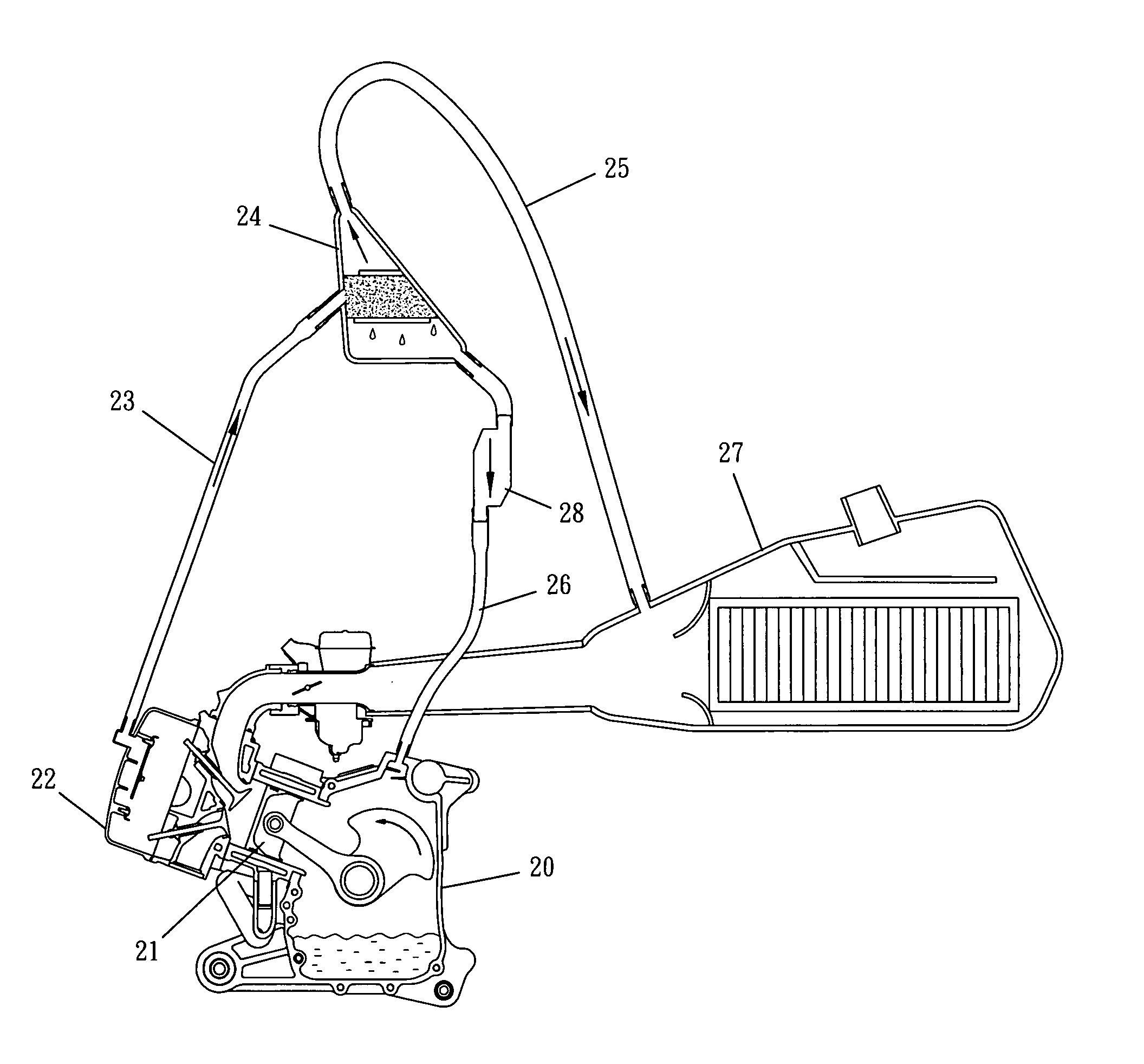
[0006]The main traits of the present invention lie in: an oil recirculation tube is additionally set up in between the bottom of the fuel-air separator and the engine, where the flow connection of the oil recirculation tube is controlled by a check valve, and the direction of the check valve is enabled only in a unidirectional way which is from the fuel-air separator to the crankcase of the engine, whereas the reverse direction is being cut off. With the integral effects out of the features of the check valve, fuel-air separator and the oil recirculation tube, the problems of carbon deposits in engine and exhaust pollution due to an excess of oil along with blow-by in the fuel-air separator can thus be improved. And the oil can be recycled to the crankcase after the separation of blow-by, which could simplify matters of watching out the liquid height of the oil preserved tube.

Problems solved by technology

As engine deteriorates, the amount of blow-by that occurs can increase.
In addition, once engine is mounted on a vehicle (for instance: all terrain vehicles, off road vehicles, etc.), it usually has sizable jolts.
And consequently the blow-by is often discharged with excessive oil.
An excess of oil burning in the combustion chamber will lead to much soot and deposits left over in the chamber that will deteriorate the engine causing great damage.

Method used


Image

  • Fuel-air separation structure improvement for engine blow-by of vehicles
  • Fuel-air separation structure improvement for engine blow-by of vehicles
  • Fuel-air separation structure improvement for engine blow-by of vehicles

Examples


Embodiment Construction

[0015]To achieve the foregoing objects and function of the present invention, the techniques and structure adopted are described with reference to the following preferred embodiments.

[0016]Referring to FIG. 3, this invention is just like prior art, where the interiors of crankcase 20 and cylinder head cover 22 of the engine are interlinked to each other. And a blow-by tube 23 is set up in between the interior of the cylinder head cover 22 and a fuel-air separator 24, where blow-by is reflowed to an air filter 27 through a blow-by recirculation tube 25 after the separation by the fuel-air separator 24. Unlike the prior art oil recirculation tube 26 set up in between the bottom of the fuel-air separator 24 and the crankcase 20 of the engine, the flow connection of the oil recirculation tube 26 is controlled by a check valve 28, and the direction of the check valve 28 is enabled only in a unidirectional way which is from the fuel-air separator 24 to the crankcase 20 of the engine, wher...


PUM


Abstract

This invention is to provide a fuel-air separation structure improvement for engine blow-by, which features an extra oil recirculation tube set up in between the bottom of the fuel-air separator and the engine, where the flow connection of the oil recirculation tube is controlled by a check valve, and the direction of the check valve is enabled only in a unidirectional way, pointing from the fuel-air separator to the crankcase of the engine, whereas the reverse direction is being cut off. By means of the aforementioned structure, the problems of carbon deposits in engine and exhaust pollution due to an excess of oil along with blow-by in the fuel-air separator can thus be substantially improved.

Description

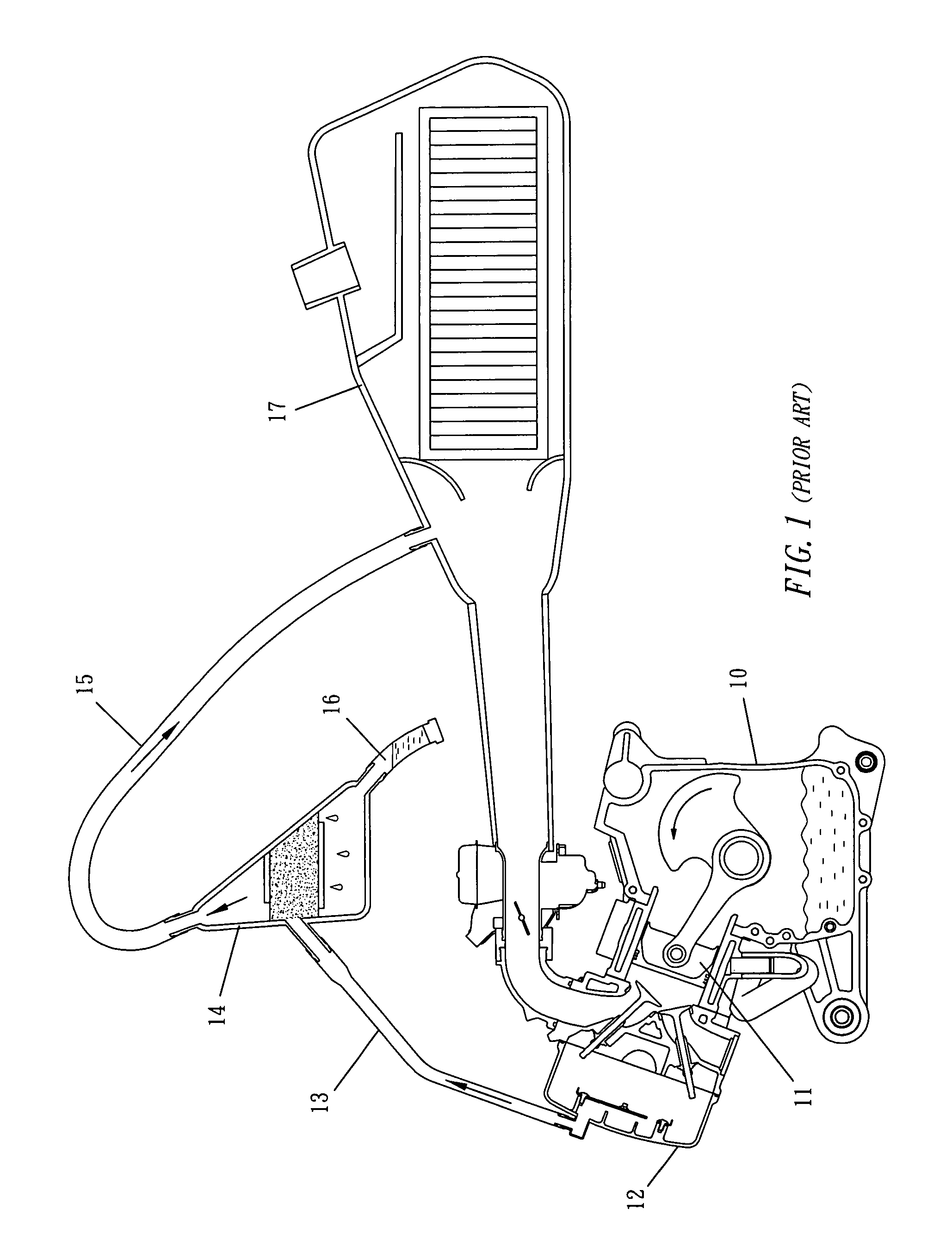
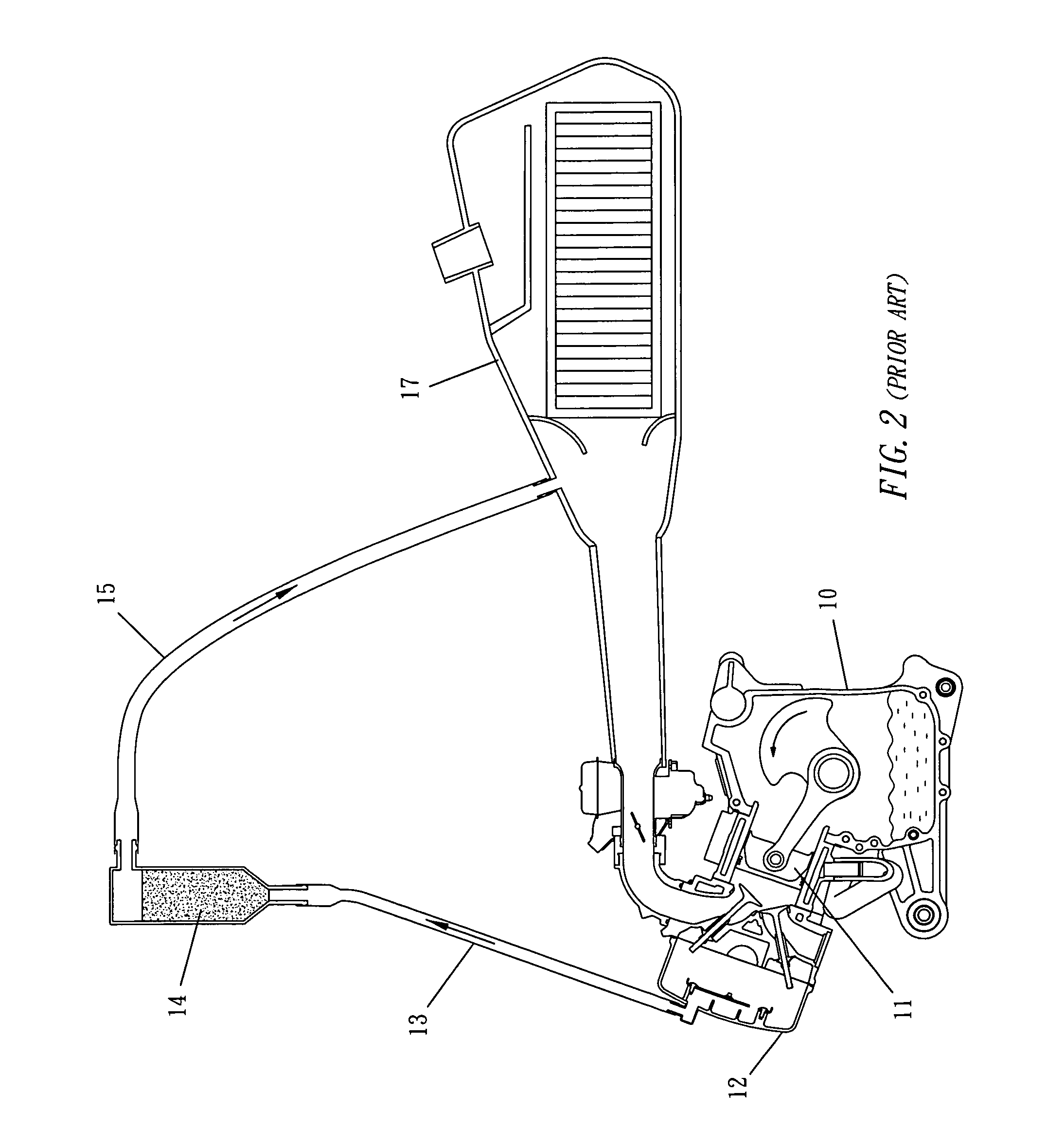
BACKGROUND OF THE INVENTION[0001]1. Field of the Invention This invention relates generally to a fuel-air separation structure improvement for engine blow-by of vehicles and more particularly to one that is able to improve the blow-by along with an excess of oil into the fuel-air separator that makes it fail to work, to avoid the derived air pollution and the increasing carbon deposits, and to abate the efficiency of the engine.[0002]2. Description of the Prior Art[0003]On the power stroke of the piston of an engine, an unburned mixture of gases slip through between cylinder wall and piston rings into the crankcase to form blow-by gases. For environmental protection sake, the unburned mixture of gases is redirected, instead of discharge, to the fuel-air separator for the separation of fuel and air, followed by burning in the combustion chamber, which is aimed at leveling down air pollution. To conduct the mixture of gases into the combustion chamber for burning, there are two approa...

Claims


Application Information

Patent Timeline
Patent Type & Authority Applications(United States)
IPC IPC(8): F02B25/06
CPCF01M1/04F01M13/023F01M13/028F01M13/04Y02T10/121F01M2013/0044F01M2013/0438F02M25/06F02M35/10222F01M13/0416Y02T10/12
Inventor LI, TONYHUANG, HUI-HUI
Owner AEON MOTOR CO LTD
Learn More