Organic photovoltaic cell

Inactive Publication Date: 2012-08-23
SUMITOMO CHEM CO LTD
View PDF3 Cites 11 Cited by
  • Summary
  • Abstract
  • Description
  • Claims
  • Application Information

AI Technical Summary

Benefits of technology

[0005]The organic solar cell that includes an UV cut film to block incident ultraviolet light can suppress deterioration of the organic material due to the ultraviolet light to elongate the lifetime of the organic solar cell. However, the technique according to Patent Docu

Problems solved by technology

However, the silicon solar cell requires a high vacuum environment and a high pressure environment in the production process to increase production cost.
However, the organic solar cell uses an

Method used


Image

  • Organic photovoltaic cell
  • Organic photovoltaic cell
  • Organic photovoltaic cell

Examples


first embodiment

9-1. First Embodiment

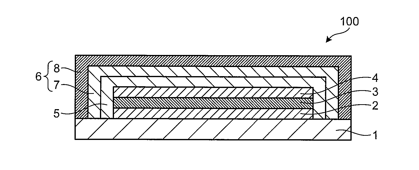
[0139]An organic photovoltaic cell 100 illustrated in FIG. 1 comprises, on a substrate 1, a first electrode 2, an active layer 3 capable of generating a charge by incident light, and a second electrode 4 in this order. Each of the first electrode 2 and the second electrode 4 is connected with a terminal not illustrated in the schematic for extracting electricity to the exterior. On a surface of the organic photovoltaic cell 100, an ultraviolet absorbing layer 5 and a barrier layer 6 are provided in this order so as to cover the organic photovoltaic cell 100 except the substrate 1. Thus, the organic photovoltaic cell 100 comprises the substrate 1, the first electrode 2, the active layer 3, the second electrode 4, the ultraviolet absorbing layer 5, and the barrier layer 6 in this order.

[0140]The barrier layer 6 comprises an inorganic layer 7 comprising an inorganic material and an organic layer 8 formed from an organic material in this order from the active layer ...

second embodiment

9-2. Second Embodiment

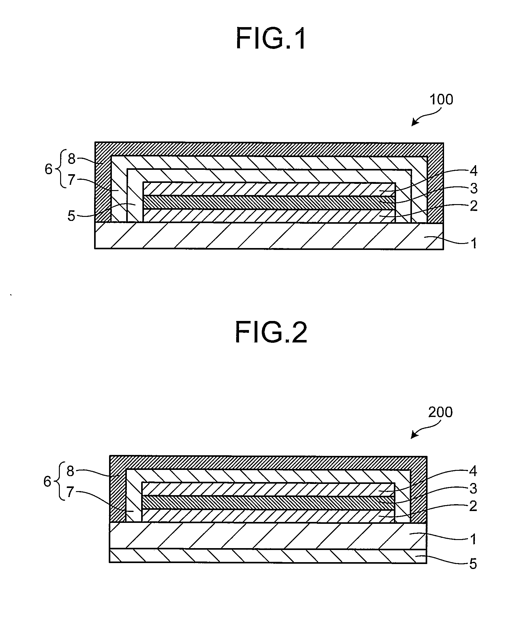
[0145]An organic photovoltaic cell 200 illustrated in FIG. 2 has the same structure as that of the organic photovoltaic cell 100 of the first embodiment except that the ultraviolet absorbing layer 5 is placed on a undersurface of the substrate 1 on a position opposite to the active layer 3 of the first electrode 2. Thus, the organic photovoltaic cell 200 comprises the ultraviolet absorbing layer 5, the substrate 1, the first electrode 2, the active layer 3, the second electrode 4, and the barrier layer 6 in this order. The inorganic layer 7 and the organic layer 8 in the barrier layer are arranged in the order of the inorganic layer 7 and the organic layer 8 from the active layer 3. One or both of the inorganic layer 7 and the organic layer 8 comprise an ultraviolet absorber to be a layer having a function of blocking ultraviolet light.

[0146]The organic photovoltaic cell 200 has the structure as described above. Hence, when light is applied onto the organic pho...

example 1

[0164]A glass substrate patterned with an ITO film having a film thickness of about 150 nm as the first electrode by a sputtering method was prepared. The prepared glass substrate was washed with an organic solvent, an alkaline detergent, and ultrapure water, then dried, and subjected to ultraviolet light-ozone treatment (UV-O3 treatment) with an UV-O3 apparatus.

[0165]A suspension of poly(3,4-ethylenedioxythiophene) / poly(styrene sulfonate) (manufactured by H.C. Starck-V TECH Ltd., Bytron P TP AI 4083) was prepared and filtered with a filter having a pore size of 0.5 μm. The filtered suspension was applied onto a surface formed with the ITO film on the glass substrate by spin coating to form a film having a thickness of 70 nm. Then, the film was dried in the atmosphere on a hot plate at 200° C. for 10 minutes to form a functional layer.

[0166]Next, an ortho-dichlorobenzene solution comprising a macromolecular compound A being an alternating polymer that was obtained by copolymerizatio...


PUM


Abstract

Provided is an organic photovoltaic cell having a long lifetime. An organic photovoltaic cell 100 comprises a first electrode 2, an active layer 3 capable of generating a charge by incident light, a second electrode 4, and a barrier layer 6 in this order. The barrier layer 6 comprises an inorganic layer 7 comprising an inorganic material and an organic layer 8 comprising an organic material. One or both of the inorganic layer 7 and the organic layer 8 have a function of blocking ultraviolet light.

Description

TECHNICAL FIELD[0001]The present invention relates to an organic photovoltaic cell.BACKGROUND ART[0002]A photovoltaic cell is a cell that can convert light energy into electric energy and an example thereof is a solar cell. The solar cell typically includes a silicon solar cell. However, the silicon solar cell requires a high vacuum environment and a high pressure environment in the production process to increase production cost. On this account, an organic solar cell has been drawing attention because the production cost of the organic solar cell is lower than that of the silicon solar cell.[0003]However, the organic solar cell uses an organic material, which is likely to deteriorate due to ultraviolet light (UV) and the like, and thus the organic solar cell tends to have shorter lifetime than that of the silicon solar cell. Hence, in order to elongate the lifetime of the organic solar cell, various techniques have been developed. For example, Patent Document 1 discloses an organic...

Claims


Application Information

Patent Timeline
IPC IPC(8): H01L31/0232
CPCB82Y10/00Y02E10/549H01L51/448H01L51/0047H10K85/215H10K30/88
Inventor KATO, TAKEHITOOHNISHI, TOSHIHIRO
Owner SUMITOMO CHEM CO LTD
Why Eureka
Try Eureka