Embedded inductor and manufacturing method thereof

a technology of embedded inductor and manufacturing method, which is applied in the direction of magnets, inductances, magnetic bodies, etc., can solve the problems of prolonging the life of molding tools, and achieve the effects of improving the insulation effect, reducing the amount of organic solvent, and increasing the bonding for

Inactive Publication Date: 2009-02-26
DELTA ELECTRONICS INC
View PDF0 Cites 11 Cited by
  • Summary
  • Abstract
  • Description
  • Claims
  • Application Information

AI Technical Summary

Benefits of technology

[0008]In view of the foregoing, the invention is to provide an embedded inductor and the manufacturing method thereof that can fully mix the magnetic material and resin to ensure the stability in the inductance and performance. In addition, the manufacturing method of the inductor of the invention does not require a high molding pressure and thus can elongate the lifetime of molding tools.
[0011]As mentioned above, the embedded inductor and the manufacturing method of the invention utilize a wet process. An insulated magnetic power is coated by a coupling agent and then mixed with a liquid resin. In comparison with the prior art, the surface-processed magnetic powder of the present invention achieves an improved insulation effect. In addition, it can reduce the amount of organic solvent when mixed with the resin, but increases the bonding force with the liquid resin so that the surface of the insulated magnetic powder can be uniformly coated by the liquid resin. This ensures the stability in inductance and performance. The inductor formed by warm pressing or hot pressing is less likely to have cracks. Because of the uniform coat of the liquid resin over the insulated magnetic powder, the output pressure during molding is stable and no high molding pressure is required. This can elongate the lifetime of molding tools.

Problems solved by technology

This can elongate the lifetime of molding tools.

Method used


Image

  • Embedded inductor and manufacturing method thereof
  • Embedded inductor and manufacturing method thereof
  • Embedded inductor and manufacturing method thereof

Examples


Embodiment Construction

[0016]The present invention will be apparent from the following detailed description, which proceeds with reference to the accompanying drawings, wherein the same references relate to the same elements.

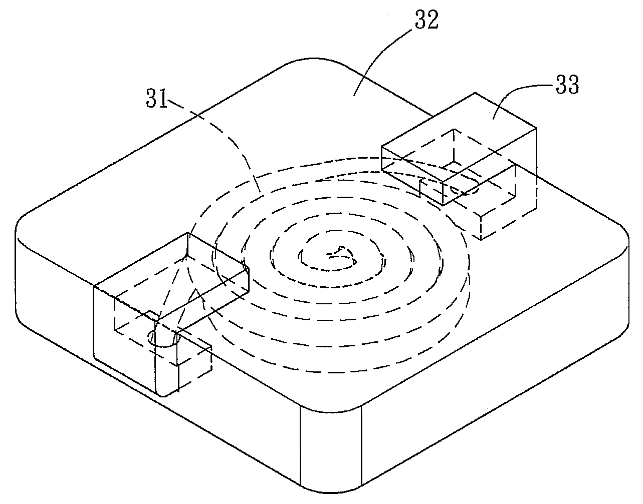
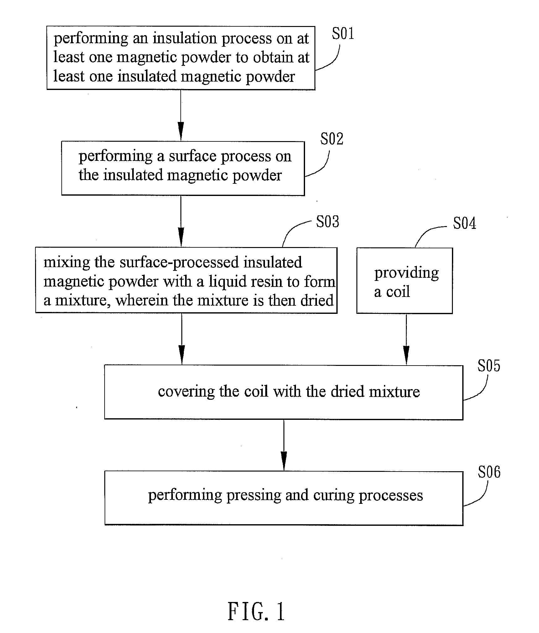
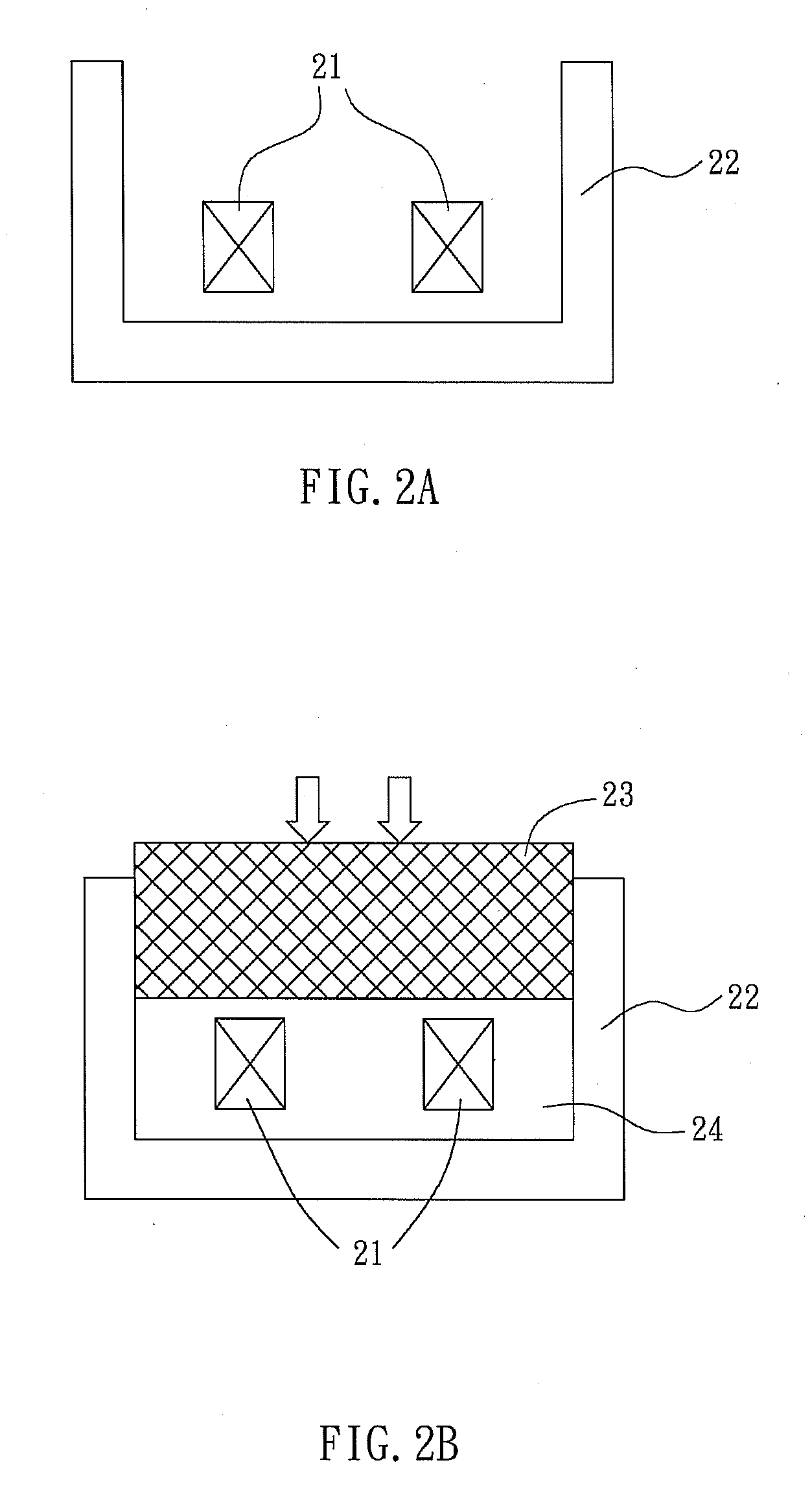
[0017]Referring to FIG. 1, a manufacturing method of an embedded inductor includes steps S01 to S06. In step S01, an insulation process is performed on a magnetic powder to obtain an insulated magnetic powder. The magnetic powder includes, for example but not limited to, iron (Fe), cobalt (Co), nickel (Ni) or their alloys. The average diameter of the magnetic powder is about 1 to 100 micron (μm). In the insulation process, the magnetic powder is coated by an inorganic material. The inorganic material includes, for example but not limited to, phosphate or a ceramic material. The ceramic material includes, for example but not limited to, aluminum oxide or zinc oxide.

[0018]In step S02, the insulated magnetic powder is processed with a surface process. The surface process utilizes a coupl...


PUM

PropertyMeasurementUnit
diameteraaaaaaaaaa
diameteraaaaaaaaaa
magneticaaaaaaaaaa

Abstract

An embedded inductor includes a coil and a magnetic body covering the coil. The magnetic body includes an insulated magnetic powder, a coupling agent and a resin. In addition, a manufacturing method of the embedded inductor includes steps of performing an insulation process for a magnetic powder to obtain an insulated magnetic powder; performing a surface process on the insulated magnetic powder; mixing the surface-processed insulated magnetic powder with a liquid resin to form a mixture; providing a coil; covering the coil with the mixture; and performing pressing and curing processes to obtain the embedded inductor.

Description

CROSS REFERENCE TO RELATED APPLICATIONS[0001]This Non-provisional application claims priority under 35 U.S.C. §119(a) on Patent Application No(s). 096131435 filed in Taiwan, Republic of China on Aug. 24, 2007, the entire contents of which are hereby incorporated by reference.BACKGROUND OF THE INVENTION[0002]1. Field of Invention[0003]The invention relates to an embedded inductor and the manufacturing thereof.[0004]2. Related Art[0005]In the development of electronic products, basic and important elements such as inductors play very important roles. Therefore, how to make high-quality inductors is one goal of the field. In view of the miniaturization trend, embedded inductors are introduced.[0006]The production method for a conventional embedded inductor is mostly dry processes. Magnetic powder and resin are mixed in a dry way before they are molded by thermal compression. Since there insufficient adhesive force between them, the resin often cannot be uniformly distributed on the mag...

Claims


Application Information

Patent Timeline
Patent Type & Authority Applications(United States)
IPC IPC(8): H01F27/02H01F7/06
CPCH01F17/04Y10T29/49073H01F2017/048
Inventor HSUEH, YU-LINLEE, CHENG-HONGHUANG, YI-HONGCHANG, LI
Owner DELTA ELECTRONICS INC
Why Eureka
Try Eureka