Memory cell comprising one MOS transistor with an isolated body having a reinforced memory effect

a memory cell and isolated body technology, applied in the field of dram-type memory cells, can solve problems such as the increase of the threshold voltage of transistors, and achieve the effect of improving the memory

Active Publication Date: 2009-06-02
STMICROELECTRONICS (CROLLES 2) SAS
View PDF7 Cites 155 Cited by
  • Summary
  • Abstract
  • Description
  • Claims
  • Application Information

AI Technical Summary

Benefits of technology

[0015]An object of the present invention is to improve this memory effect.

Problems solved by technology

At the end of this state, as illustrated in FIG. 3B, the space charge areas tend to be wider, which results in an increase in the transistor threshold voltage.

Method used


Image

  • Memory cell comprising one MOS transistor with an isolated body having a reinforced memory effect
  • Memory cell comprising one MOS transistor with an isolated body having a reinforced memory effect
  • Memory cell comprising one MOS transistor with an isolated body having a reinforced memory effect

Examples


Embodiment Construction

[0031]As usual in the representation of integrated circuits, the various cross-section views are not drawn to scale.

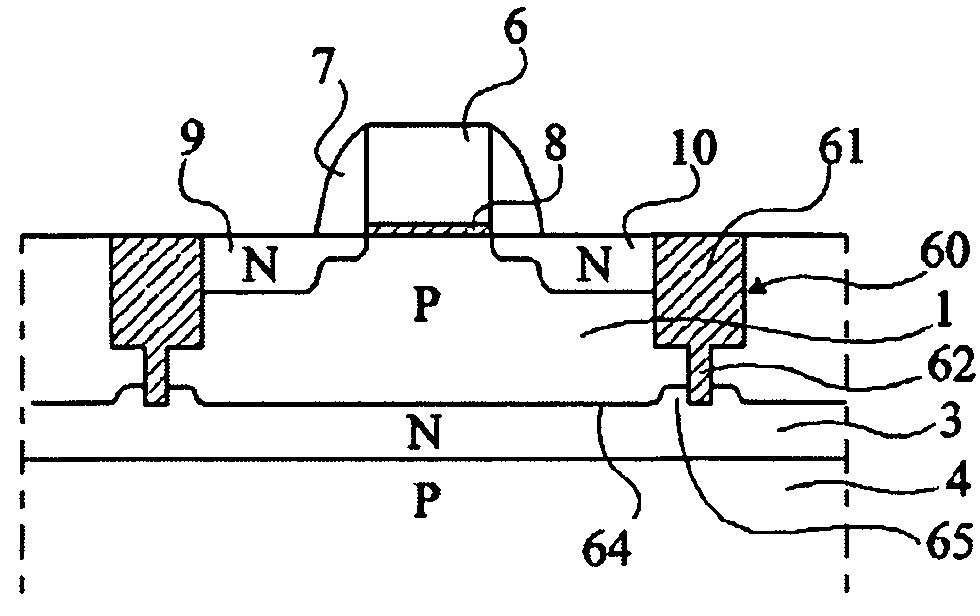
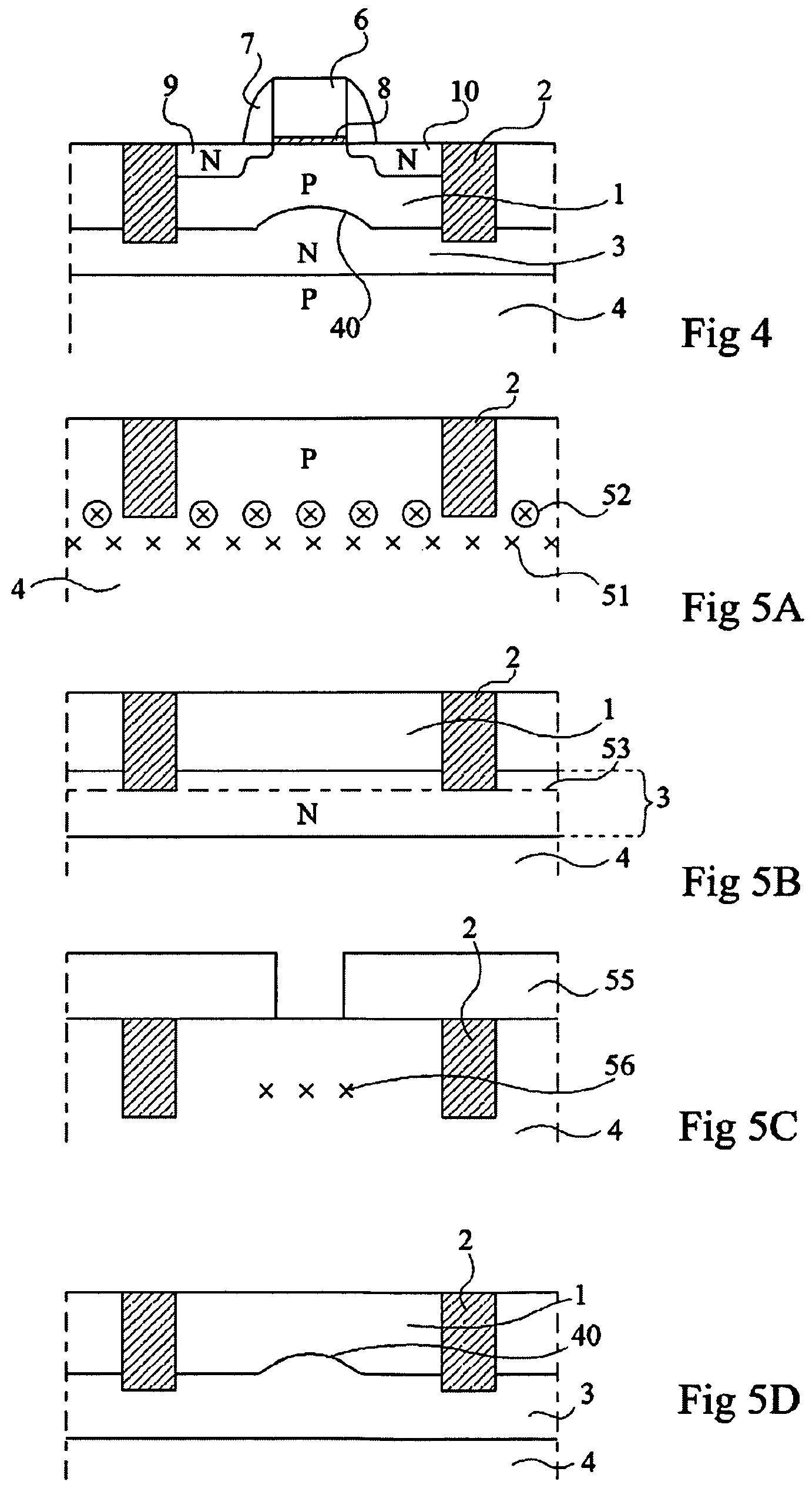
[0032]FIG. 4 shows, in a simplified cross-section view, an example of a memory cell with a transistor on a floating body according to an embodiment of the present invention. In this drawing, the same elements as in FIG. 1 are designated with the same reference numerals. In this cross-section view, no conductive area enabling creating a contact with buried layer 3, said contact being outside of the plane of the drawing or being common to a cell block, has been shown.

[0033]In this embodiment of the present invention, the junction surface between floating body 1 and buried layer 3 is non-planar. It exhibits a protrusion 40 substantially under the gate area of the MOS transistor. This results in increasing the junction surface with respect to the prior art case illustrated in FIG. 1 where the junction is planar.

[0034]The inventors have shown that such an increase in the ju...


PUM


Abstract

A memory cell with one transistor on a floating body region isolated by its lower surface by a junction. According to the present invention, the junction is non-planar and, for example, includes a protrusion directed towards the transistor surface.

Description

BACKGROUND OF THE INVENTION[0001]1. Field of the Invention[0002]The present invention generally relates to DRAM-type memory cells with one transistor formed in a floating body or well delimited depthwise by a junction.[0003]2. Discussion of the Related Art[0004]FIG. 1 is a simplified cross-section view of an example of such a memory cell. This cell comprises an N-channel MOS transistor formed in a floating body region 1 laterally delimited by an isolating ring 2 and, depthwise, by an N-type layer 3 formed in a P-type substrate 4. The MOS transistor comprises, on either side of a gate region 6 surrounded with spacers 7 and resting on a gate insulator 8, N-type source and drain regions 9 and 10. Each of the source and drain regions comprises a deeper more heavily doped region outside of the region defined by spacers 7 and a shallower less heavily doped region under spacers 7.[0005]In the absence of a specific action on the cell, floating body 1 is at a given voltage corresponding to t...

Claims


Application Information

Patent Timeline
Patent Type & Authority Patents(United States)
IPC IPC(8): H01L29/78
CPCG11C11/404H01L27/108H01L27/10802H01L29/7841G11C2211/4016H10B12/20H10B12/00
Inventor RANICA, ROSSELLAVILLARET, ALEXANDREMAZOYER, PASCALE
Owner STMICROELECTRONICS (CROLLES 2) SAS
Why Eureka
Try Eureka