Image forming device and network system

a network system and image forming technology, applied in the field of image forming devices, can solve the problem of not being able to easily modify the display content in the settings window, and achieve the effect of facilitating the editing of display conten

Active Publication Date: 2009-06-02
BROTHER KOGYO KK
View PDF34 Cites 11 Cited by
  • Summary
  • Abstract
  • Description
  • Claims
  • Application Information

AI Technical Summary

Benefits of technology

[0008]In view of the foregoing, it is an object of the present invention to provide an image forming device and a network system that facilitates the editing of display content in a settings window for a plurality of functions possessed by the image forming device.

Problems solved by technology

However, since the average user does not know the rules of HTML, the average user cannot overwrite this Hypertext content and, therefore, cannot easily modify display content in the settings window, such as the order in which setting items are displayed.

Method used


Image

  • Image forming device and network system
  • Image forming device and network system
  • Image forming device and network system

Examples


first embodiment

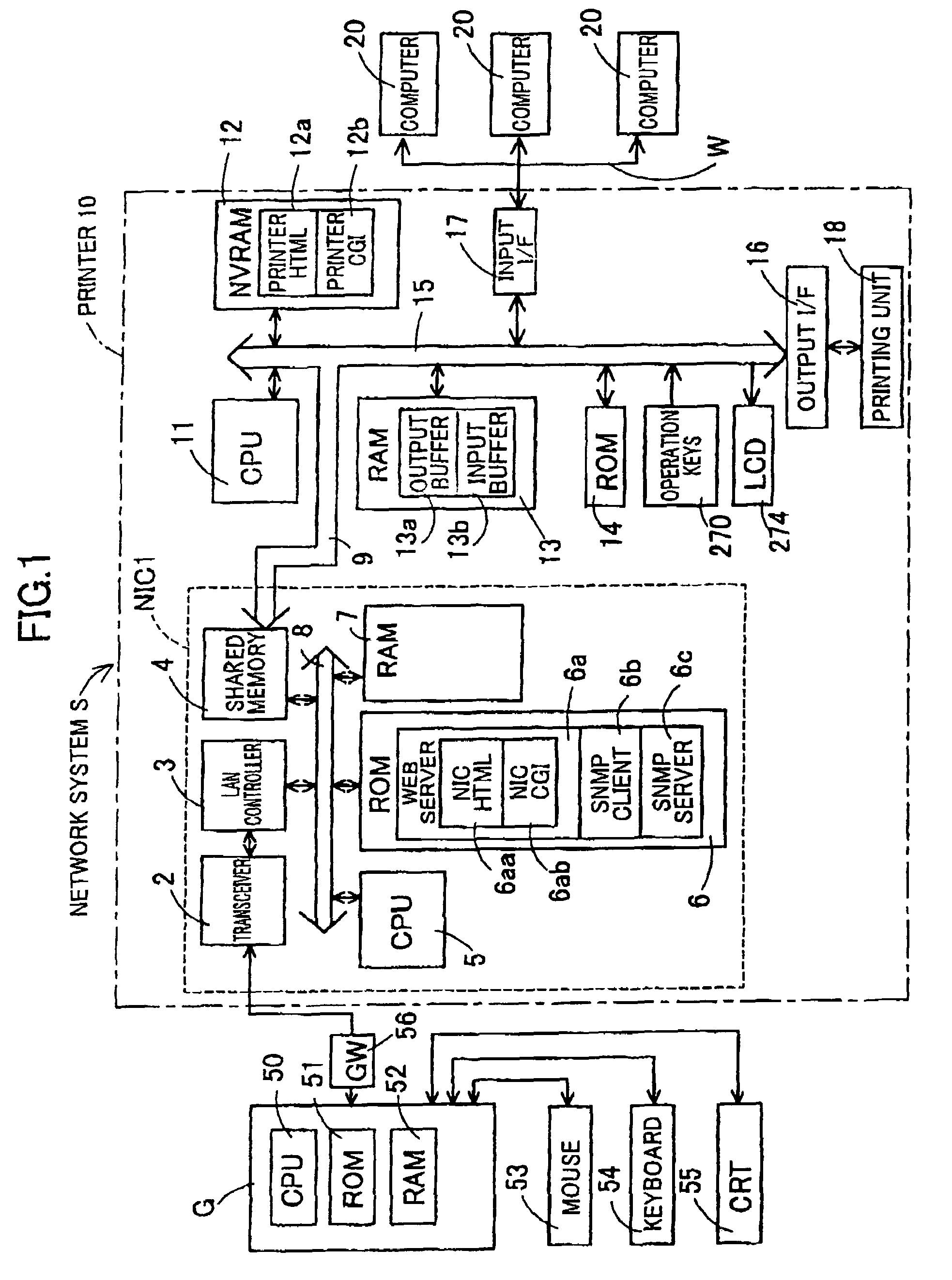
[0023]First, the general construction and use of the printer 10 according to the first embodiment will be described with reference to FIG. 1FIG. 1 is a block diagram showing the general construction and use of the printer 10 according to the first embodiment.

[0024]Generally speaking, the World Wide Web (WWW) is an information system that enables a separate administrative computer G to manage all network administration data for the printer 10. The administrative computer G includes a program called a web browser for browsing the status of settings and the like for the terminal device 10. The administrative computer G manages the network system S by accessing and learning the status of the printer 10. The administrative computer G renders image- and text-data using software links called hypertext to show the status of the printer 10. HTTP (HyperText Transfer Protocol) is used as the protocol for communications between the administrative computer G and the printer 10. Further, HTML (Hy...

second embodiment

[0080]Next, a printer according to a second embodiment will be described with reference to FIGS. 5 and 6 with like parts and components designated by the same reference numerals to avoid duplicate description.

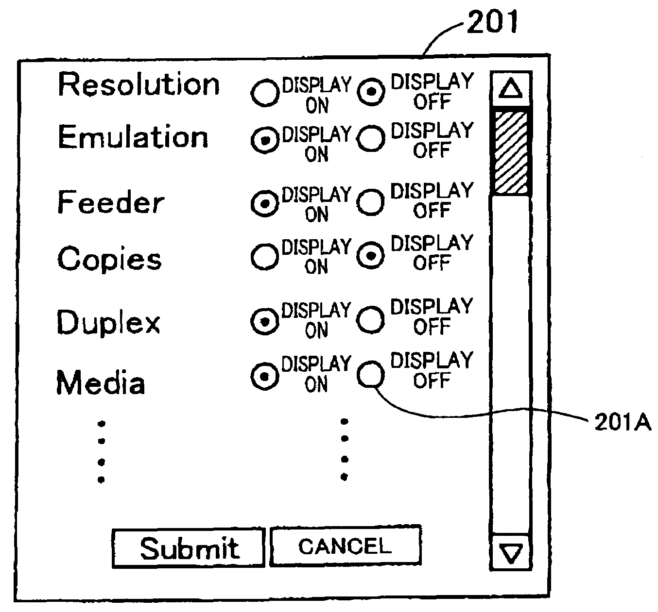
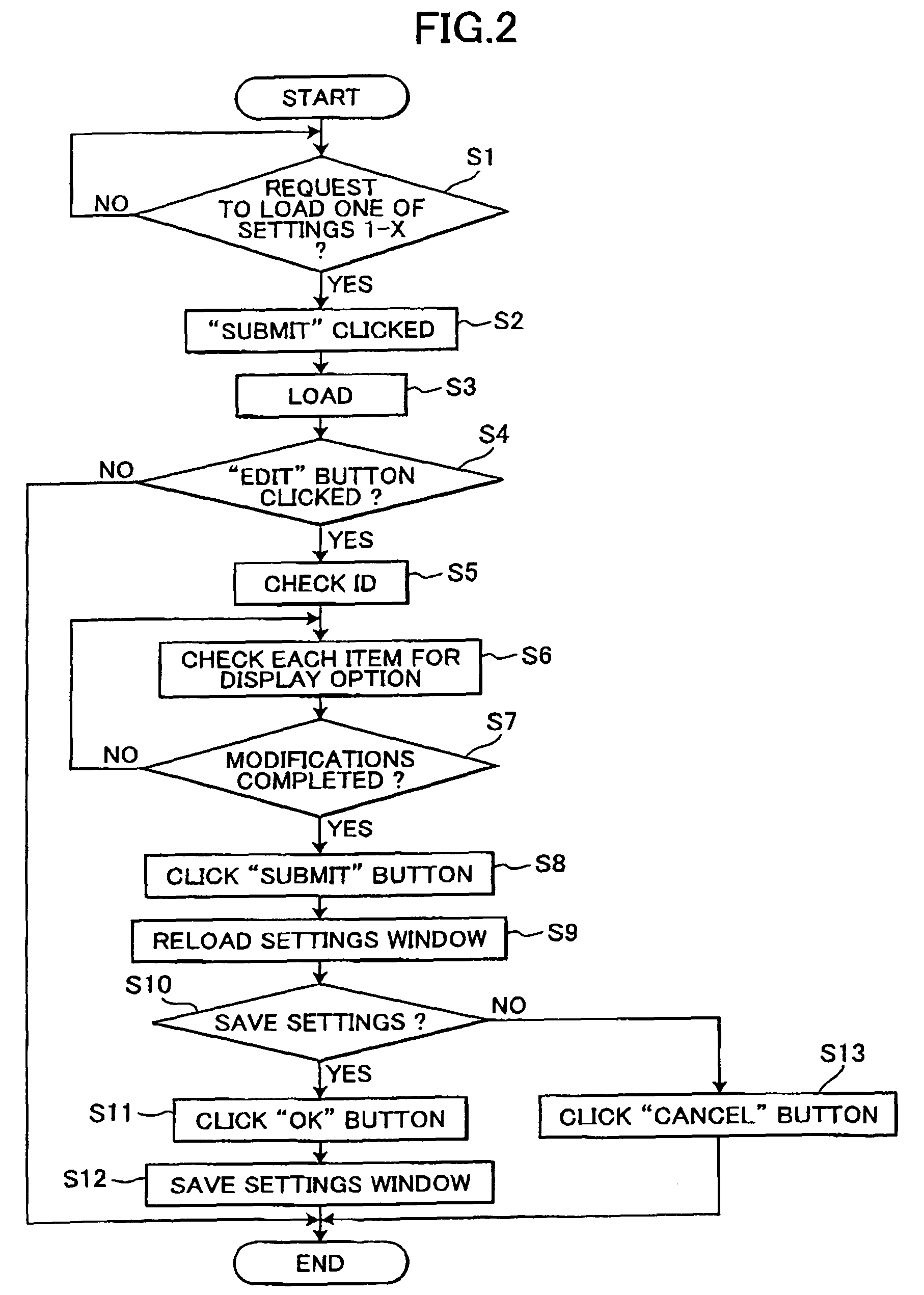
[0081]FIG. 5 is a main flow chart showing an example of the edit controlling process in which the CPU 11 of the printer 10 according to the second embodiment modifies setting items displayed in the print function settings wizard that is transmitted to the administrative computer G or the computers 20. FIG. 6 is an explanatory diagram showing an example edit wizard used to modify settings data displayed in the print function settings wizard on the screen of the administrative computer G or the computers 20 according to the second embodiment.

[0082]The overall construction of the printer according to the second embodiment and the construction of the control circuit are substantially identical to the printer 10 according to the first embodiment. However, the printer according to th...

third embodiment

[0094]Next, a printer according to a third embodiment will be described with reference to FIGS. 7 and 8, wherein like parts and components have the same reference numerals to avoid duplicate description.

[0095]FIG. 7 is a main flowchart showing an edit controlling process executed by the CPU 11 to modify via the LCD 274 setting items to be displayed in the print function settings wizard 202 to be transmitted to the computer G or 20. FIG. 8 is an explanatory diagram showing an example display on the LCD 274 when modifying setting items to be displayed in the print function settings wizard 202 according to the third embodiment.

[0096]The overall construction of the printer according to the third embodiment and the construction of the control circuit are substantially identical to the construction of the printer 10 according to the first embodiment. However, the printer according to the third embodiment differs from the printer 10 according to the first embodiment in that setting items t...


PUM


Abstract

When the printer 10 receives a request signal from one of the administrative computer G and the computers 20 indicating that the user has used the mouse 53 to click the “Edit” button displayed on the CRT monitor 55 (S4), then the printer 10 transmits data for the edit wizard 201 for modifying setting items displayed in the print function settings wizard 202 to the administrative computer G or the computer 20 corresponding to the ID data set attached to the request signal. The user uses the mouse 53 to click on either “Display on” or “Display off” next to each setting item in the edit wizard 201 displayed on the CRT monitor 55 (S6), enabling the user to re-edit setting items displayed in the print function settings wizard 202 (S7-S13).

Description

BACKGROUND OF THE INVENTION[0001]1. Field of the Invention[0002]The present invention relates to an image forming device connected to a network system.[0003]2. Description of Related Art[0004]Image forming devices such as laser printers that are connected to a network store setting items such as printing conditions and their setting values in a Hypertext format as display data. A browser program can display this display data on a display unit of the image forming device as a settings window or a settings screen. In a printing device disclosed in Japanese unexamined patent application publication No. 2001-166907, for example, Hypertext display data stored in the printing device is transferred to a personal computer connected to the printing device via a network. By so doing, a browser program provided on the personal computer can display the display data of the printing device in a display unit of the personal computer as a settings window.[0005]By overwriting the Hypertext content (...

Claims


Application Information

Patent Timeline
Patent Type & Authority Patents(United States)
IPC IPC(8): G06F7/00B41J29/38G06F3/12
CPCG06F3/1205G06F3/1246G06F3/1253G06F3/1285Y10S707/99931
Inventor YAMADA, AKIHIRO
Owner BROTHER KOGYO KK
Why Eureka
Try Eureka