2D and 3D display system and method for furnace tube inspection
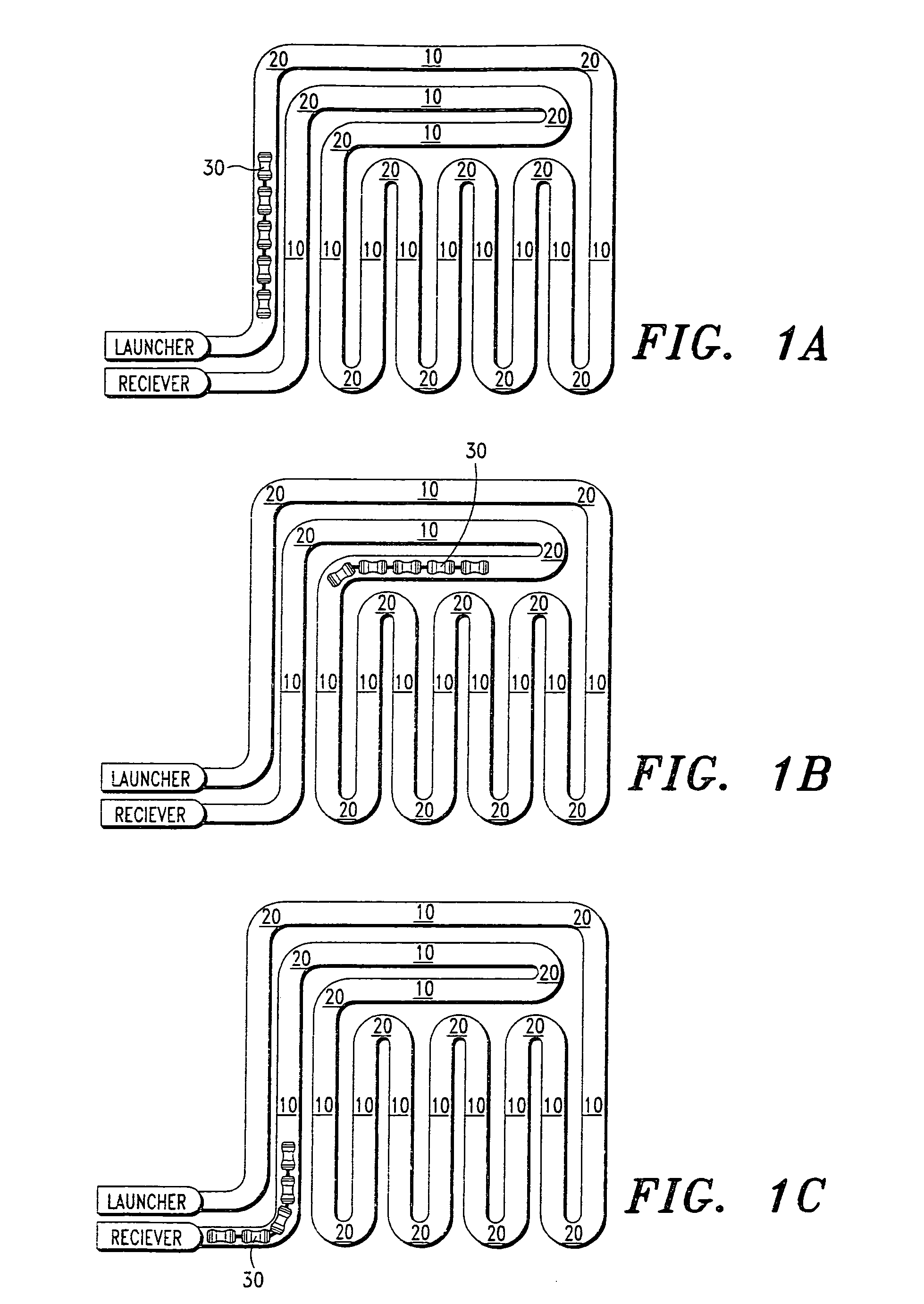
a technology of display system and furnace tube, which is applied in the direction of furnaces, instruments, nuclear elements, etc., can solve the problems of difficult correlation of inspection data collected from the furnace with the physical geometry of the furnace, inspection tools may take longer to traverse a bend in the furnace, and inspection tools often ebb and flow through the furnace, etc., to facilitate the observation of trends and rapid assessment of problem areas
- Summary
- Abstract
- Description
- Claims
- Application Information
AI Technical Summary
Benefits of technology
Problems solved by technology
Method used
Image
Examples
example 1
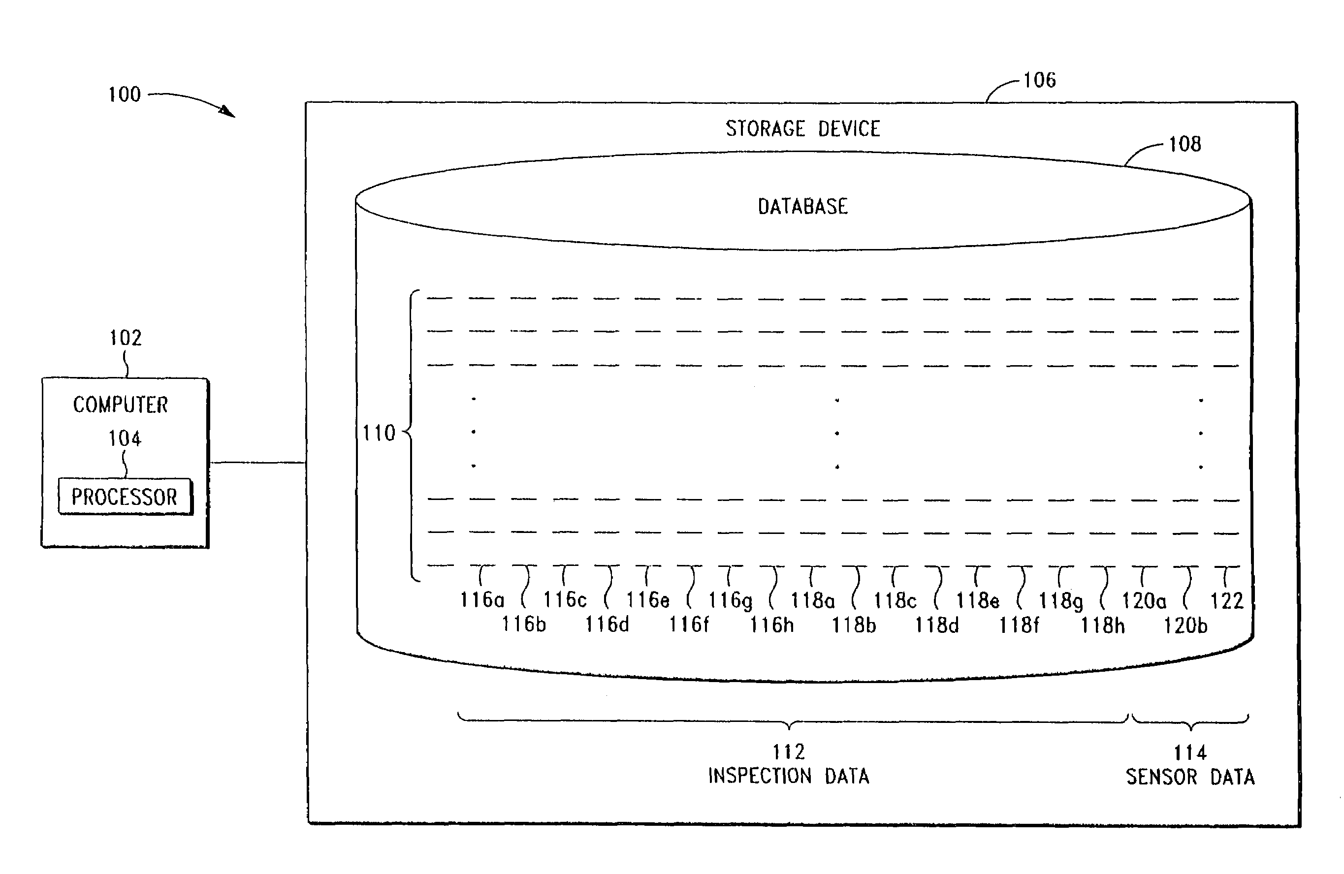
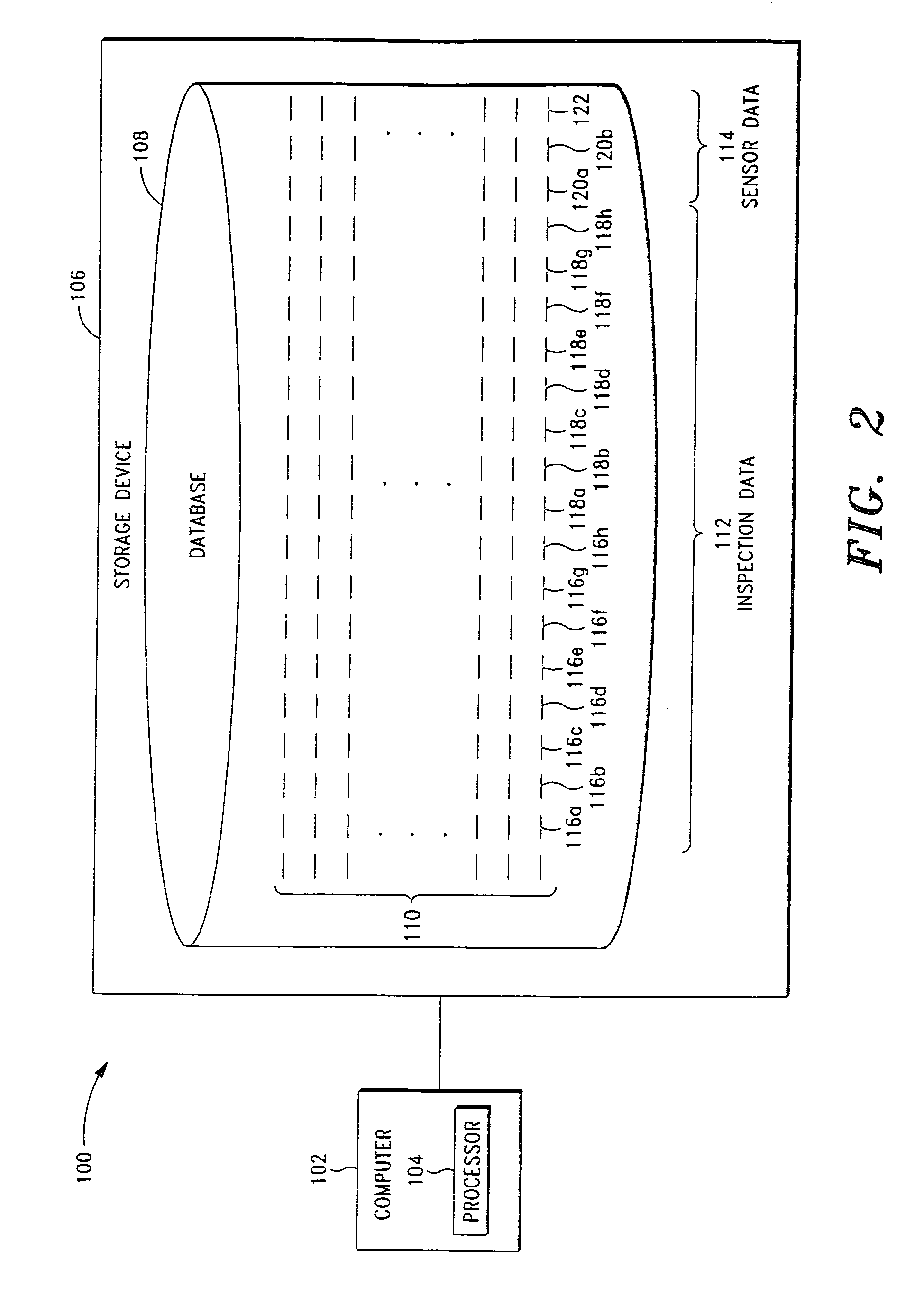
[0052]In this example, computer 102 is programmed to generate a two-dimensional display of the wall thickness readings and / or inside radius readings collected from a furnace, which may be viewed by a data analyst in order to identify the locations of the furnace bends. Then, based upon input from the data analyst, computer 102 is programmed to generate a plurality of data markers on the display to thereby correlate the various readings to the appropriate tube segments of the furnace. After generation of the data markers, the data analyst may view the display in order to visually detect problems areas within the furnace. This example will now be described in greater detail with reference to FIGS. 3 and 4.
[0053]Referring to FIG. 3, computer 102 is programmed to generate a strip chart 300 in which all of the wall thickness readings for a plurality of time intervals are plotted across a plurality of horizontal strips. The wall thickness readings are plotted successively in time from lef...
example 2
[0062]In this example, computer 102 is programmed to generate a two-dimensional display of the wall thickness readings collected from the convection section of a furnace, whereby the display may be viewed by a data analyst in order to visually detect problems areas within the furnace. Specifically, computer 102 is programmed to generate the chart shown in FIG. 5, in which all of the wall thickness readings for a plurality of time intervals are plotted across a plurality of vertical bars. Each vertical bar displays the wall thickness readings from a single tube segment. The tube segments are positioned in their proper orientation (but with the connecting bends removed).
[0063]In this example, the wall thickness readings displayed on the chart are color-coded in accordance with a color legend, wherein the readings range from 3 mm (shown in dark red) to 10 mm (shown in dark blue). It should be understood that the wall thickness readings may alternatively be represented in gray scale (as...
example 3
[0065]In this example, computer 102 is programmed to generate a two-dimensional display of the wall thickness readings collected from the convection section of another furnace, whereby the display may be viewed by a data analyst in order to visually detect problems areas within the furnace. Specifically, computer 102 is programmed to generate the chart shown in FIG. 6, in which all of the wall thickness readings for a plurality of time intervals are plotted across a plurality of vertical bars. Similar to the chart of FIG. 5, each vertical bar displays the wall thickness readings from a single tube segment, wherein the tube segments are positioned in their proper orientation (but with the connecting bends removed).
[0066]In this example, the wall thickness readings displayed on the chart are color-coded in accordance with a color legend, wherein the readings range from 0.20 inches (shown in dark red) to 0.45 inches (shown in dark blue). Again, while the wall thickness readings may alt...
PUM
 Abstract
Description
Claims
Application Information
 - R&D
- Intellectual Property
- Life Sciences
- Materials
- Tech Scout
- Unparalleled Data Quality
- Higher Quality Content
- 60% Fewer Hallucinations
Browse by: Latest US Patents, China's latest patents, Technical Efficacy Thesaurus, Application Domain, Technology Topic, Popular Technical Reports.
© 2025 PatSnap. All rights reserved.Legal|Privacy policy|Modern Slavery Act Transparency Statement|Sitemap|About US| Contact US: help@patsnap.com


