Method and system for dynamic analysis of complex systems

a dynamic analysis and complex system technology, applied in the field of computer-aided engineering, to achieve the effect of optimizing the acoustic and/or vibrational behaviour of complex systems and efficient studying the dynamic analysis of complex systems

Active Publication Date: 2009-06-02
SIEMENS IND SOFTWARE NV
View PDF3 Cites 13 Cited by
  • Summary
  • Abstract
  • Description
  • Claims
  • Application Information

AI Technical Summary

Benefits of technology

[0009]It is an object of the present invention to provide a system and method for efficiently studying the dynamic analysis of complex systems. Such system and method can be e.g. advantageously used for optimising the acoustic and / or vibrational behaviour of complex systems.
[0010]The above objective is accomplished by a method and device according to the present invention. The invention relates to a method for performing dynamic analysis of a system, the method comprising sub-structuring of said system into a plurality of sub-structures, modelling said sub-structures into sub-structure models and modelling interfaces between said sub-structure models, combining said sub-structure models at the interfaces into a combined system and solving the combined system, wherein said modelling comprises performing a dynamic analysis on a discretised model of at least a subassembly of at least two sub-structures. The latter allows to obtain an efficient system. The computational time needed, e.g. in a modification and / or optimisation study of a complex system, can significantly be reduced.

Problems solved by technology

The difficulty is to choose the reduction basis such that for the qualities of interest similar results are obtained as for full models.

Method used


Image

  • Method and system for dynamic analysis of complex systems
  • Method and system for dynamic analysis of complex systems
  • Method and system for dynamic analysis of complex systems

Examples


first embodiment

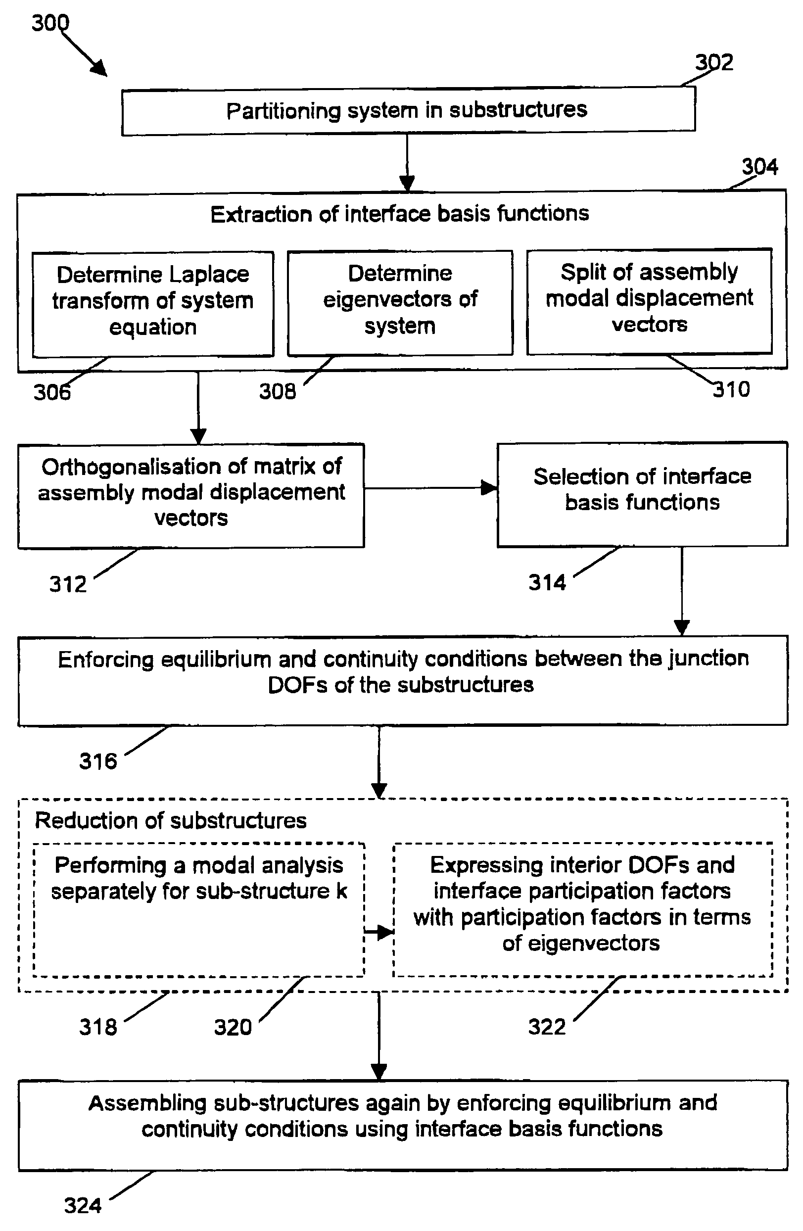
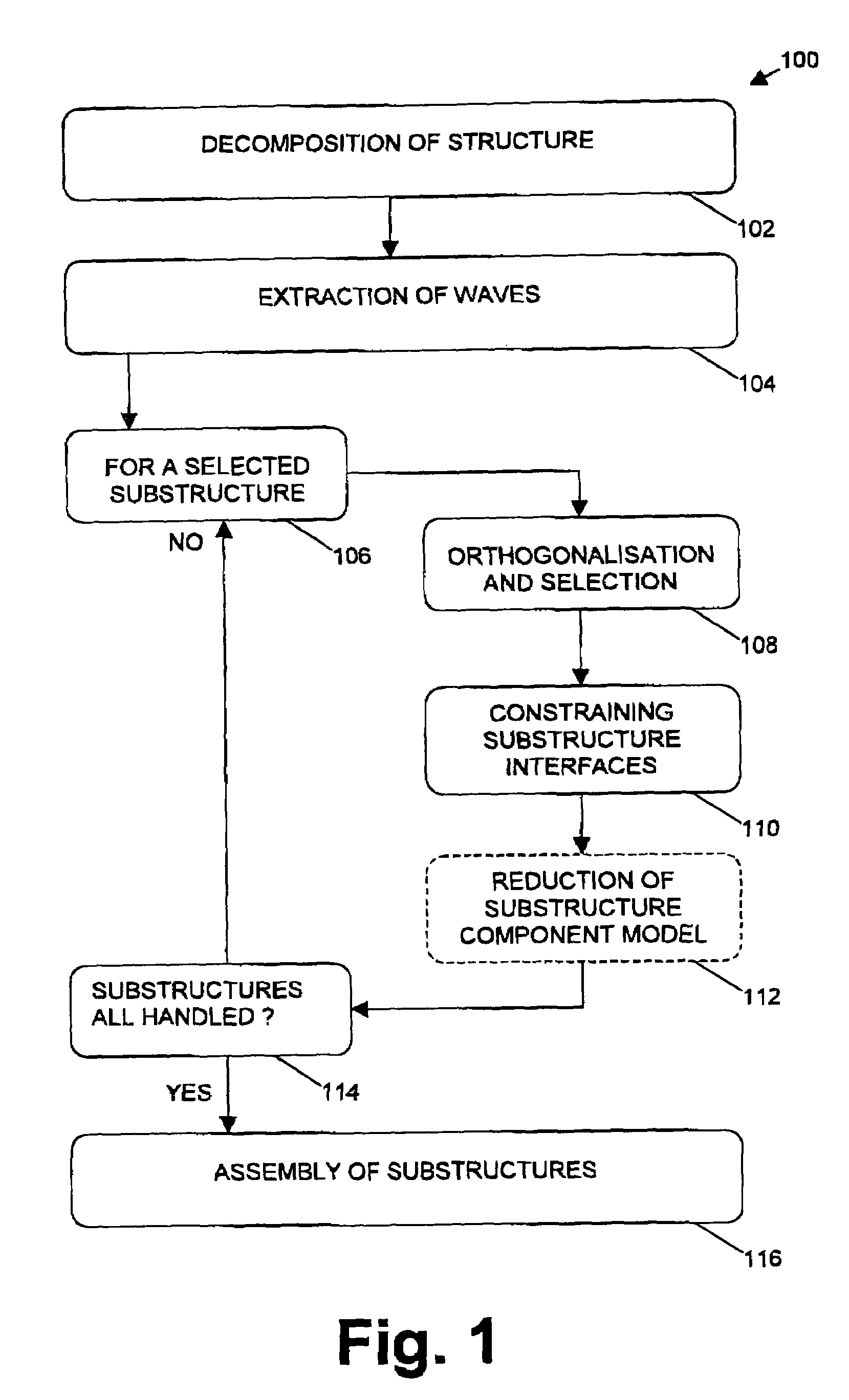
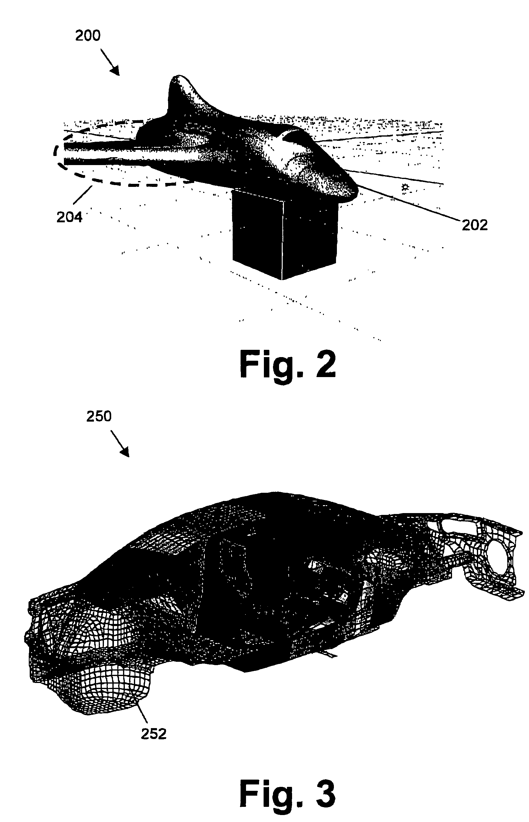
[0051]In a first embodiment, the present invention relates to a method for efficient wave sub-structuring in the dynamic analysis of complex systems. The method 100 comprises a number of steps, which by way of illustration are shown in the flow chart of FIG. 1. The different objects used while performing the method for studying properties of a spacecraft are described in FIG. 2. It is to be noted that the latter is only provided by way of illustration, the invention not being limited thereto. In a first step 102, the original system 200 is decomposed into two or more sub-structures 202. The term substructure 202 thereby can be defined as a part of the system 200 or a physical element of the system 200. In a second step 104, extraction of the interface basis functions is performed. The interface basis functions also may be referred to as waves. The interface basis functions thereby are defined through a generalised eigenvector calculation on the original discretised model for the com...

second embodiment

In order to assemble two sub-structures a and b thus requires enforcing the general interface flexibility matrix {circumflex over (K)}pro on the participation factors pa and pb that define the junction between sub-structure a and sub-structure b, that in general has a different number of junction DOFs Naj and Nbj. It should be noted that a sub-structure k hereby can be a full finite element model. In that case, the participation factors pk are embedded in a constraint relation equation [11]. In case the sub-structure is reduced, the participation factors pk are embedded in the sub-structure's modal displacement vectors in equation [13] that consist of the natural modes ψkcnr and optionally also additional enrichment vectors, e.g. residual vector modes ψkcresr, the latter being described in more detail in the This makes no difference for the procedure. The equilibrium and continuity equations are always defined between the participation factors pa and pb that define the junction bet...


PUM


Abstract

Methods for performing a dynamic analysis of complex systems are described. The dynamic analysis of complex systems is performed by sub-structuring of the system into a plurality of sub-structures. The sub-structures and the interfaces between the sub-structures are modelled using a generalized eigenvector analysis of a discretized model of a full system or a subassembly thereof comprising at least two sub-structures. The sub-structures then are combined at the interfaces into a combined system. The combined system then is solved. Optionally, selected sub-structures may be reduced. Performing such a dynamic analysis allows studying characteristics such as e.g. vibration and / or acoustical effects in a computational efficient way. Such methods can be applied for optimizing designs of such complex systems.

Description

TECHNICAL FIELD OF THE INVENTION[0001]The present invention relates to Computer-Aided Engineering (CAE) and in particular to Computer-Aided Engineering (CAE) methods and apparatus for studying physical properties of a system. The physical properties of a system can e.g. be the acoustic and / or vibration behaviour of a system.BACKGROUND OF THE INVENTION[0002]Vibration effects and acoustic performance of manufactured products, such as for example, but not limited to, transportation means, has become a very important aspect in the design and development process of new products, not only to improve the comfort of the user of the product, e.g. passengers in a car or in an aircraft, but also to reduce the nuisance to the surroundings, e.g. for habitations close to highways or to an airport. The additional trend of mass customisation furthermore forces engineers to evaluate and design a higher number of transportation means variants on a lower number of platforms. The design decisions there...

Claims


Application Information

Patent Timeline
Patent Type & Authority Patents(United States)
IPC IPC(8): G06F17/10G06F17/50
CPCG06F17/5018G06F17/5095Y02T10/82G06F30/23G06F30/15Y02T90/00
Inventor BRUGHMANS, MARCMAS, PETERHADJIT, RABAHBRECHLIN, EIKEDONDERS, STIJN
Owner SIEMENS IND SOFTWARE NV
Why Eureka
Try Eureka