
Lift chair and recliner

a recliner and lift chair technology, applied in the field of recliner chairs and lift chairs, can solve the problems of having no means for changing the position of the backrest, limited number of recliner positions that can be achieved with such chairs, and limited range of motion, so as to achieve comfortable and versatile recliner

Active Publication Date: 2009-06-09
GOLDEN TECH
View PDF29 Cites 72 Cited by
  • Summary
  • Abstract
  • Description
  • Claims
  • Application Information

AI Technical Summary

Benefits of technology

Enables a chair that can be positioned in multiple reclining and lift positions, providing comfort and support by relieving spine pressure, improving circulation, and allowing users to easily stand up, with enhanced maneuverability and adjustability.

Problems solved by technology

However, the drive mechanism is connected between the chair frame and a pair of arm members that comprise part of the main support structure of the chair, rather than between the chair and seat frames, and therefore suffers from the disadvantage of having a limited range of motion.
While the linkage system for such chair enables it to be moved to a conventional television viewing position and a resting position, there is no means for changing the position of the backrest independently of the position of the seat frame or footrest.
The back frame, however, is not independently movable, and therefore the number of reclining positions that can be achieved with such chair are substantially limited.
The linkage of the chair back frame to the seat frame does not allow for independent movement of the chair back, however.
None of such arrangements appears to allow for completely independent adjustment of the back frame, however.
The linkage mechanism used, however, does not appear to provide the same maneuverability of the back section recliner as is possible with the present inventors' arrangement.
However, the seat still must move forwardly for the back to move to a fully reclined position, and there is no means for independently pivoting the backrest with respect to the seat portion.
The linkage system does not provided for independent movement of the backrest, however.
Such chair, which is the subject of several related patents, does not appear to disclose a motor actuated system for independently adjusting the position of the backrest.
The chair back cannot be reclined independent of the seat frame, however.
However, such motor appears to be connected on its other end to the chair frame rather than the seat, and therefore would not provide the same advantages available in the present disclosure.

Method used


Image

  • Lift chair and recliner
  • Lift chair and recliner
  • Lift chair and recliner

Examples


Embodiment Construction

[0076]The following detailed description is of the best mode or modes of the invention presently contemplated. Such description is not intended to be understood in a limiting sense, but to be an example of the invention presented solely for illustration thereof, and by reference to which in connection with the following description and the accompanying drawings one skilled in the art may be advised of the advantages and construction of the invention.

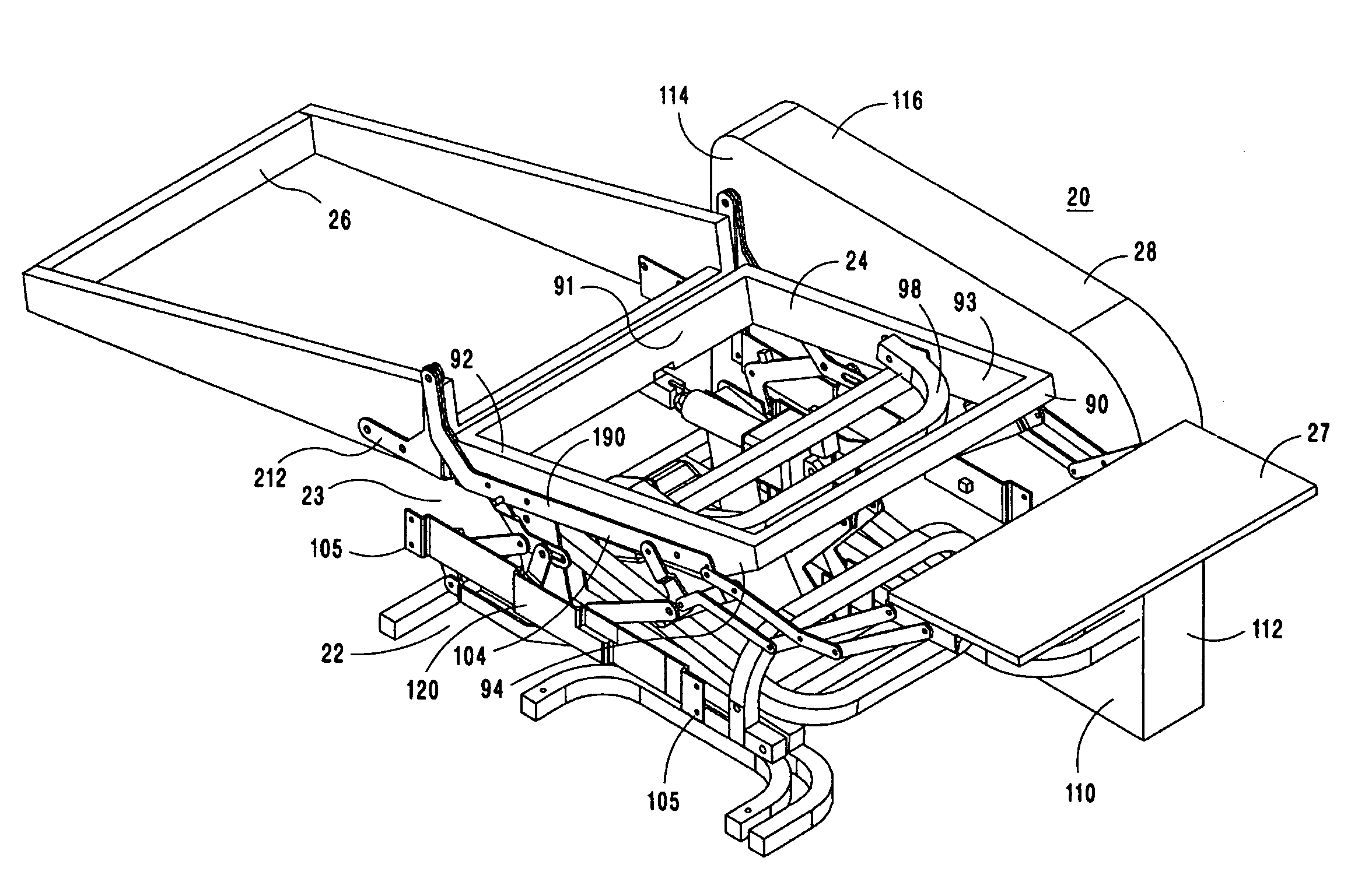
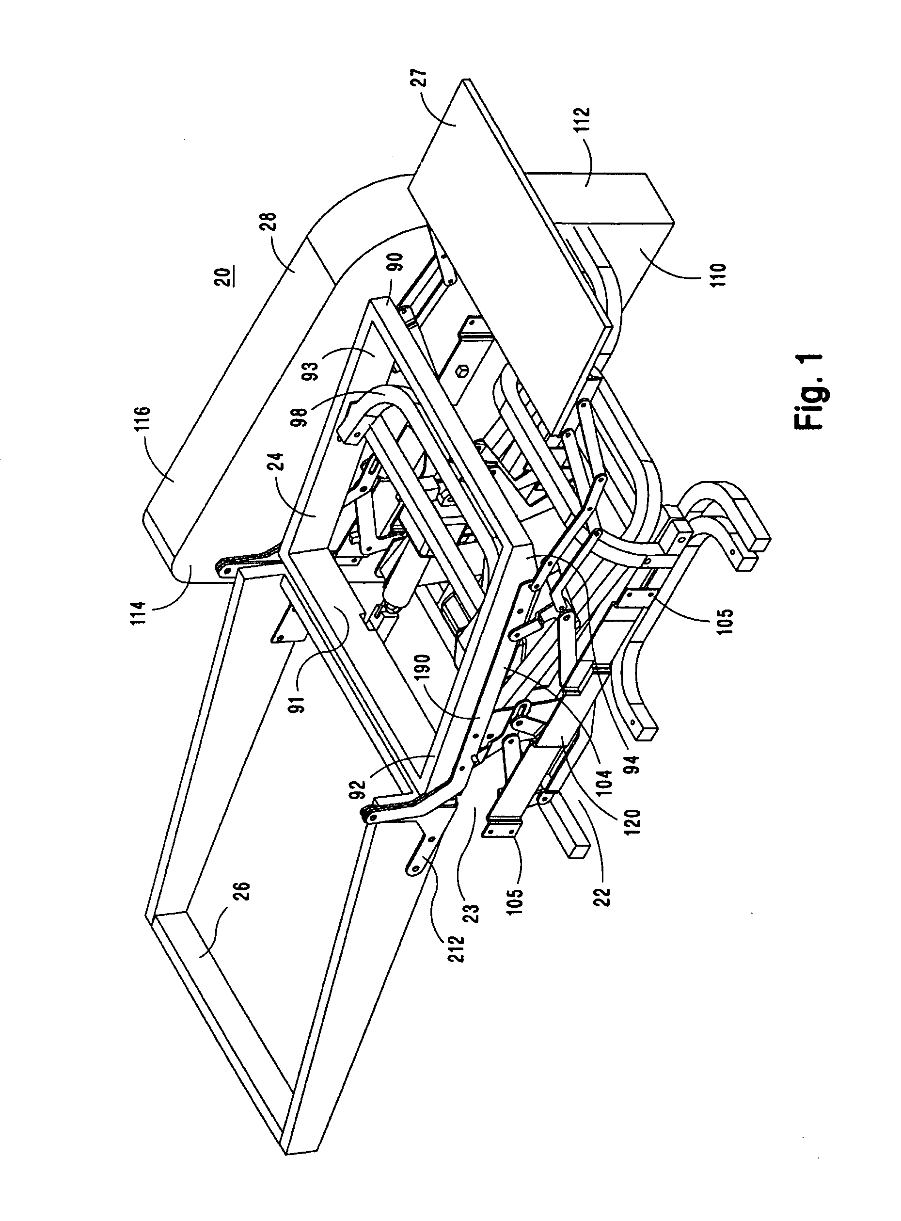
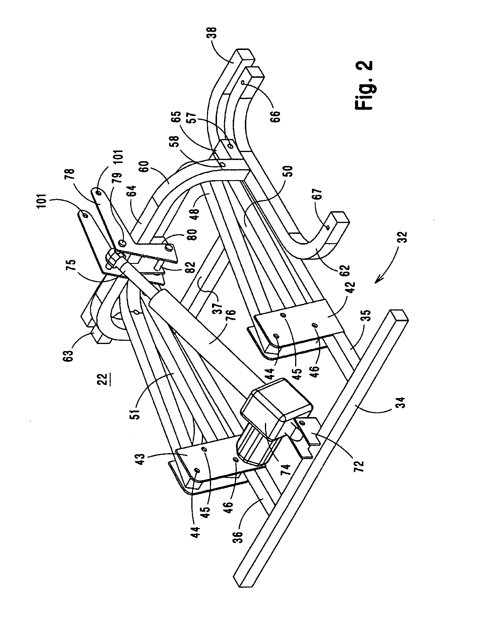
[0077]FIGS. 1-12 and 15-24 illustrate a first embodiment of the present invention, FIGS. 13-14 illustrate a second embodiment wherein a preferred chair backframe pivot mechanism is disclosed, and FIGS. 25-28 illustrate another preferred embodiment of such chair backframe pivot mechanism. Referring first to FIG. 1, there is shown a perspective view of chair 20 of the invention in a reclined position, with the right arm frame, from the point of view of a chair occupant, and all of the upholstery removed to illustrate the components of the ...


PUM


Abstract

A combination lift chair and reclining chair having additional seating and reclining positions is provided with two separate motors and linkages enabling the chair back to be independently placed in various positions and the seat separately movable with the footrest and elevated once the footrest has reached full deployment using the same motor.

Description

CROSS-REFERENCE TO PREVIOUS RELATED APPLICATION[0001]This invention claims priority from U.S. Provisional Patent Application Ser. No. 60 / 609,415, filed on Sep. 13, 2004, the complete disclosure of which is incorporated herein by reference.BACKGROUND OF THE INVENTION[0002]1. Field of the Invention[0003]The present invention relates to chairs in general, and more particularly to recliner chairs and lift chairs, and more particularly still to a recliner or lift chair wherein the back frame is movable independent of the seat frame and footrest, and can be positioned in both a zero gravity and Trendelenburg position.[0004]2. Preliminary Discussion[0005]Recliner chairs and lift chairs have been on the market for years, with the utility of recliners being primarily for use in living rooms and family rooms, while lift chairs are used by the handicapped, elderly, or disabled to assist them in moving from a reclined or sitting position to a standing position. While a substantial number of tod...

Claims


Application Information

Patent Timeline
Patent Type & Authority Patents(United States)
IPC IPC(8): A47C1/02A47C1/0355A61G5/14
CPCA47C1/0355A47C31/008A61G5/14A61G5/006A61G5/1075A61G7/005A47C1/0242A47C1/034A47C1/035A47C1/024
Inventor POLLARD, WARREN EDWARDOLCHESKI, JAMES
Owner GOLDEN TECH
Learn More