Multiwall vented bag, vented bag forming apparatus, and associated methods

a technology of vented bags and vented ends, applied in the field of multi-wall packaging and methods for forming multi-wall packaging, can solve the problems of unvented bags bursting during stacking process, bag handling and stacking difficulty, and significant difficulty

Inactive Publication Date: 2006-01-17
HOOD PACKAGING
View PDF70 Cites 20 Cited by
  • Summary
  • Abstract
  • Description
  • Claims
  • Application Information

AI Technical Summary

Benefits of technology

[0011]In view of the foregoing, an embodiment of the present invention advantageously provides a multiwall vented bag and associated methods that allow a vented bag to be easily constructed and yet substantially reduces the risk of filler material sifting from the bag and of insects infesting the bag through vents in the bag. An embodiment of the present invention also advantageously provides a multiwall vented bag that enhances stacking ability and yet allows air trapped in the bag to be readily vented therefrom. An embodiment of the present invention further advantageously provides end product packaging that is sealable and includes a vented assembly built onto and inner tube formed of plastic material that permits air release after the bag is packed and an open end of the bag and a plastic pouch have been sealed. An embodiment of the present invention also advantageously provides a multiwall vented bag of tubular form having a continuous unseamed tube body to enhance manufacturing and handling and to enhance reliability. Further embodiments of the present invention advantageously provide user friendly bags capable of holding products of varying weights, that are strong and durable, that provide consumers with a venting capability that will allow air release to accommodate the handling and stacking the bag for shipment, will reduce the possibility of product leakage or infestation, and will be cost effective and easy to manufacture.
[0014]The present invention also advantageously provides an end product packaging bag according to an embodiment thereof and includes a tube formed of at least one ply of plastic material and having an open-end, a closed end positioned opposite the open end, a tube body extending between the open end and the closed end, and at least one vent opening, e.g., preferably a plurality of vent openings, formed in the tube body. The tube is adapted to be sealed to closure at its opposite ends. The bag also includes a plastic strip positioned adjacent and attached to a preselected region of the tube body including the at least one vent opening of the tube. The plastic strip also includes at least one vent opening, e.g., also preferably a plurality of vent openings, and is positioned to allow air to pass from within the inner tube body, through both the at least one vent opening of the tube body and the at least one vent opening of the plastic strip. The combination of the plastic strip and the preselected region of the tube body define a vent seal zone positioned to permit air release after the bag has been filled with filler material and the open end of the bag has been sealed. The vent seal zone also can include a channel space positioned between a surface of the plastic strip and a surface of the tube body. The channel space allows air to flow therethrough and extends between the at least one vent opening of the tube body and the at least one vent opening of the plastic strip so that the at least one vent opening of the tube and the at least one vent opening of the strip are not aligned and thereby form a tortuous path to significantly reduce the risk of insect infestation and to significantly reduce product sifting when product is positioned in the bag.
[0017]The present invention also includes methods of forming and using a bag. For example, according to an embodiment of the present invention, a method of forming a vented bag includes perforating a tube of at least one ply of plastic material to form a plurality of spaced apart vent openings in the tube, perforating a separate plastic strip of material to form a plurality of spaced apart vent openings in the plastic strip, and adhering the plastic strip adjacent the tube in a preselected region to thereby form a vented seal zone having a channel space formed between surfaces of the plastic strip and the tube so that the combination of the plurality of vent openings in the tube and the plurality of vent openings in the plastic strip are positioned to not align so as to create a tortuous path to significantly reduce product sifting and insect infestation when product is positioned within the tube and so that air within the tube travels through both of the plurality of vent openings in the tube and the plurality of vent openings in the plastic strip.
[0018]Another method of forming a vented bag includes positioning a plate member within a tube of at least one ply of plastic material and rotatingly perforating the tube with a perforator roll positioned adjacent a first outer surface of the plate member so that the plate member operates as a stop for the perforator roll to prevent perforation of a second opposing outer surface of the tube and yet allowing perforation of the first outer surface of the tube to form a plurality of spaced apart vent openings in the first outer surface of the tube. The method can also include perforating a separate plastic strip of material to form a plurality of spaced apart vent openings in the plastic strip and adhering the plastic strip adjacent the tube in a preselected region to thereby form a vented seal zone having a channel space formed between surfaces of the plastic strip and the tube so that the combination of the plurality of vent openings in the tube and the plurality of vent openings in the plastic strip are positioned to not align so as to create a tortuous path to reduce product sifting and insect infestation when product is positioned within the tube and so that air within the tube travels through both of the plurality of vent openings in the tube and the plurality of vent openings in the plastic strip.
[0019]Another example of an embodiment of a method of using a multiwall bag having a vent seal zone associated therewith includes filling first and second multiwall bags with filler material. Each of the first and second multiwall bags have an inner plastic tube, a vent seal zone formed by a plastic strip attached to a preselected region of the inner plastic tube, and an outer tube formed of a plurality of layers of porous material attached to and substantially surrounding the inner tube. The inner plastic tube has a plurality of spaced-apart vent openings and the plastic strip includes a plurality of spaced-apart vent openings not aligned with the plurality of space-apart vent openings of the inner plastic tube so as to create a tortuous path therebetween. The vent seal zone also includes a channel space positioned between a surface of the plastic strip and a surface of the inner tube body. The method also includes closing each of an open end of the first and second multiwall bags after filler material is filled therein and stacking the second multiwall bag to overlie and contact the first multiwall bag so that pressure from weight of the second multiwall bag increases the air flow from the inner tube of the first multiwall bag, through both the plurality of vent openings in the inner tube and the plurality of openings in the plastic strip, and through the porous material of the outer tube to atmosphere.

Problems solved by technology

A significant difficulty arises, however, when air is trapped in the inner pouch of the bag prior to sealing.
Applicants have recognized that when the plastic liner inside an unvented bag is sealed after being filled, it traps air and causes the bag to be difficult to handle and stack.
There is also the risk that end seals in unvented bags will rupture during stacking processes due to excess pressure being applied.
This problem is accentuated where the facility filling the bags is located at a different pressure altitude than a destination facility.
Vents made by piercing a single ply plastic pouch or liner have been found to be ineffective as they allow material to sift out and insects to infest the material inside which often consists of food or pharmaceutical grade product.
Applicants have recognized that these type of seamed bags, however, can have problems with seam overlap alignment and can be complex to manufacture.
Applicants have recognized that additional problems can be encountered with this type of bag arrangement, however.
This can cause uneven or excessive pressures on the lower plastic seal creating a potential for seal failure or pinholing.

Method used


Image

  • Multiwall vented bag, vented bag forming apparatus, and associated methods
  • Multiwall vented bag, vented bag forming apparatus, and associated methods
  • Multiwall vented bag, vented bag forming apparatus, and associated methods

Examples


Embodiment Construction

[0040]The present invention will now be described more fully hereinafter with reference to the accompanying drawings, which illustrate embodiments of the invention. This invention may, however, be embodied in many different forms and should not be construed as limited to the illustrate embodiments set forth herein. Rather, these embodiments are provided so that this disclosure will be thorough and complete, and will fully convey the scope of the invention to those skilled in the art. Like numbers refer to like elements throughout. Prime notation, if used, indicates similar elements in alternative embodiments.

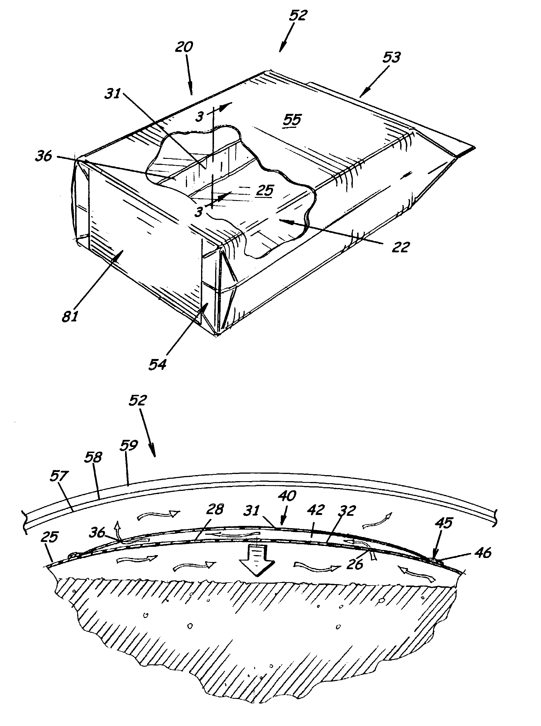
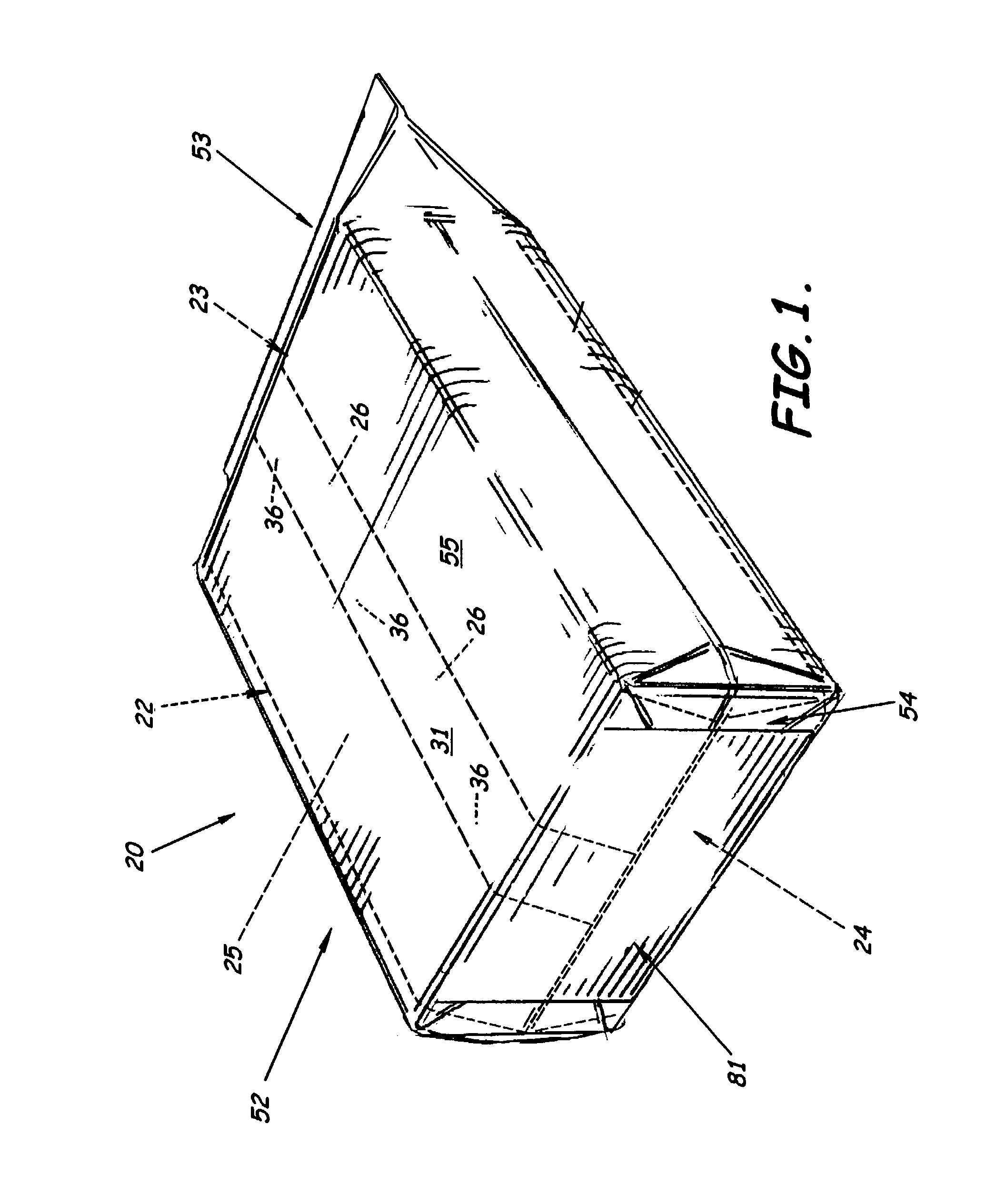
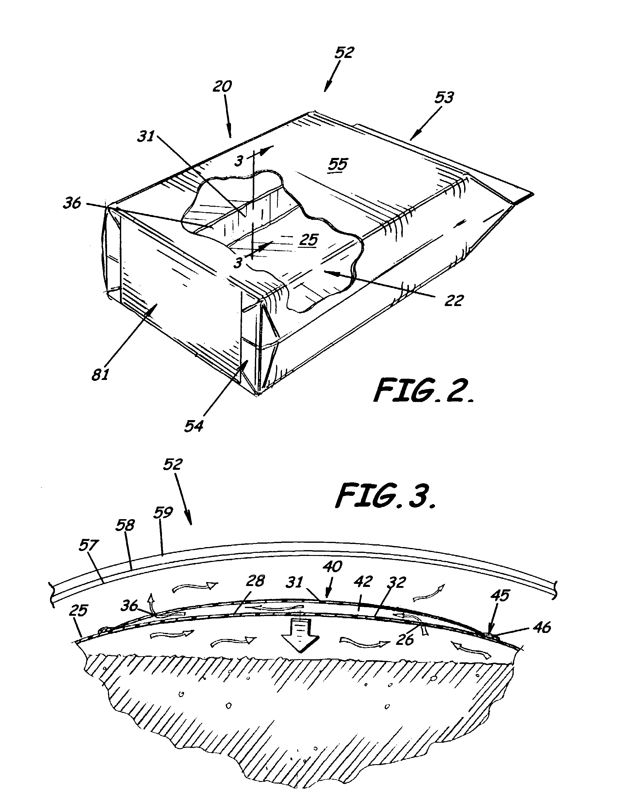
[0041]As illustrated in FIGS. 1–17, embodiments of the present invention advantageously provide a multiwall bag 20, e.g., a plurality of overlying layers or plies of material. The bag includes an inner tube 22 formed of a plastic material, e.g., such as supplied from a roll of plastic tube material 27 (see FIGS. 1–2 and 6). In a preferred embodiment of the bag 20, the plastic ma...


PUM


Abstract

A multiwall vented bag is provided which includes an inner tube formed of a plastic material. The inner tube has an open end initially in an open position and adapted to receive filling material therein and at least one vent opening formed therein. The bag further includes a strip of material positioned adjacent and attached to a preselected region of the inner tube. The preselected region includes the at least one vent opening of the inner tube. The strip also includes at least one vent opening to allow air to pass from within the inner tube, through both the at least one vent opening of the inner tube and the at least one vent opening of the strip. The bag further includes an outer tube positioned to substantially surround outer surfaces of the inner tube. The outer tube is formed of a porous material that allows air released from within the inner tube to pass out of the bag through porous material of the outer tube. A method of forming and using a vented bag are also included.

Description

BACKGROUND OF THE INVENTION[0001]1. Field of the Invention[0002]The present invention relates generally to the packaging industry. In more specific aspects, the present invention relates to multiwall packaging and methods for forming multiwall packaging that have vents associated therewith.[0003]2. Description of the Related Art[0004]As more and more industrial, commercial, and consumer products are packaged, the need for enhanced end product packaging continues to grow. End product packaging not only has to keep the products fresh, the product packaging often needs to protect the environment from the product contents and protect the product contents from the environment. The packaging must also be strong enough to hold materials of varying weights, without being damaged, in order to provide packaging for a vast array of consumer products.[0005]Of particular importance is often the ability to extract the contents of a package such as a bag without contaminating the contents with a c...

Claims


Application Information

Patent Timeline
Patent Type & Authority Patents(United States)
IPC IPC(8): B65D33/01B65D30/08
CPCB65D33/01
Inventor ALLEN, JOHN R.BUSBIN, RICHARD HENRY
Owner HOOD PACKAGING
Why Eureka
Try Eureka