Capacitor pairs with improved mismatch performance

a technology of capacitor pairs and mismatch performance, which is applied in the direction of semiconductor devices, semiconductor/solid-state device details, electrical apparatus, etc., can solve the problems of capacitor pairs cb>1/b> and cb>2/b> mismatch from each other, and worsen the mismatch performance of capacitor pairs, so as to reduce the sensitivity to process variations and increase the relative capacitance mismatch

Active Publication Date: 2009-06-09
TAIWAN SEMICON MFG CO LTD
View PDF3 Cites 9 Cited by
  • Summary
  • Abstract
  • Description
  • Claims
  • Application Information

AI Technical Summary

Benefits of technology

[0012]The embodiments of the present invention have the advantageous feature of lowered sensitivity to process variations. A greater capacitor pair can thus be formed without increasing relative capacitance mismatches.

Problems solved by technology

As a result, capacitors C1 and C2 mismatch from each other.
Using a CMP process worsens the mismatch performance of capacitor pairs if the capacitor pairs have high capacitances.

Method used


Image

  • Capacitor pairs with improved mismatch performance
  • Capacitor pairs with improved mismatch performance
  • Capacitor pairs with improved mismatch performance

Examples


Embodiment Construction

[0022]The making and using of the presently preferred embodiments are discussed in detail below. It should be appreciated, however, that the present invention provides many applicable inventive concepts that can be embodied in a wide variety of specific contexts. The specific embodiments discussed are merely illustrative of specific ways to make and use the invention, and do not limit the scope of the invention.

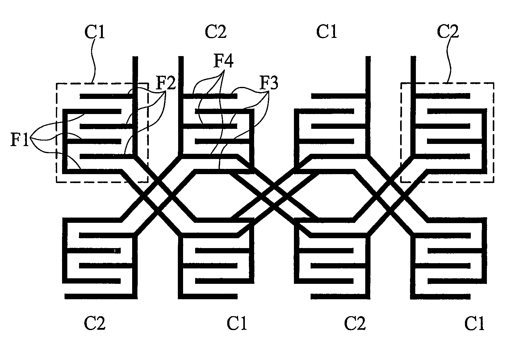
[0023]FIG. 3 illustrates a top view of an embodiment of the present invention, which includes eight unit capacitors arranged as a two-by-four array. Four of the interconnected unit capacitors are marked as C1, and the other four interconnected unit capacitors are marked as C2. Unit capacitors C1 and C2 are designed to have identical capacitances. Unit capacitors C1 and unit capacitors C2 are placed in an alternating pattern, hence making a checkerboard pattern. Each unit capacitor comprises a first set of interconnected metal lines (referred to as fingers hereinafter) and a s...


PUM


Abstract

A semiconductor device includes a first capacitor comprising a plurality of first unit capacitors interconnected to each other, each having a first unit capacitance; and a second capacitor comprising a plurality of second unit capacitors interconnected to each other, each having a second unit capacitance, wherein the first unit capacitors and the second unit capacitors have equal numbers of unit capacitors. The first unit capacitors and the second unit capacitors are arranged in an array with rows and columns and placed in an alternating pattern in each row and each column. The first and the second unit capacitors each have a total number greater than two.

Description

TECHNICAL FIELD[0001]This invention relates generally to semiconductor devices, and more particularly to the design and manufacturing methods of capacitor pairs.BACKGROUND[0002]In modern integrated circuits, such as circuits for mixed-mode or radio-frequency applications, a pair of capacitors with equal capacitances is commonly used. The mismatched performance of the capacitor pair determines the accuracy of the resulting digital signal, and thus capacitor pairs with highly matched capacitances are preferred.[0003]FIG. 1 illustrates a conventional capacitor pair, which includes a first capacitor C1 and a second capacitor C2. Capacitors C1 and C2 are identically designed. Each of the capacitors C1 and C2 include a first plurality of fingers and a second plurality of fingers alternately placed. The capacitances of capacitors C1 and C2 are partially determined by the length and number of fingers. Greater capacitors C1 and C2 can be designed by increasing the number of fingers and / or by...

Claims


Application Information

Patent Timeline
Patent Type & Authority Patents(United States)
IPC IPC(8): H01L29/00
CPCH01L23/5223H01L27/0805H01L2924/0002H01L2924/00
Inventor CHEN, CHIA-YICHANG, CHUNG-LONGCHAO, CHIH-PING
Owner TAIWAN SEMICON MFG CO LTD
Why Eureka
Try Eureka