Guided control of a transporter

a technology of guided control and transporter, which is applied in the direction of bicycles, wheelchairs/patient conveyances, battery/cell propulsion, etc., can solve the problems of no longer being useful to the rider and the rider cannot control the motion of the transporter, and achieve the effect of facilitating the turning of the transporter

Inactive Publication Date: 2009-06-16
DEKA PROD LLP
View PDF151 Cites 51 Cited by
  • Summary
  • Abstract
  • Description
  • Claims
  • Application Information

AI Technical Summary

Problems solved by technology

Once a rider dismounts from such a transporter, the rider cannot control the transporter's motion by leaning and the transporter is no longer useful to the rider.

Method used


Image

  • Guided control of a transporter
  • Guided control of a transporter
  • Guided control of a transporter

Examples


Embodiment Construction

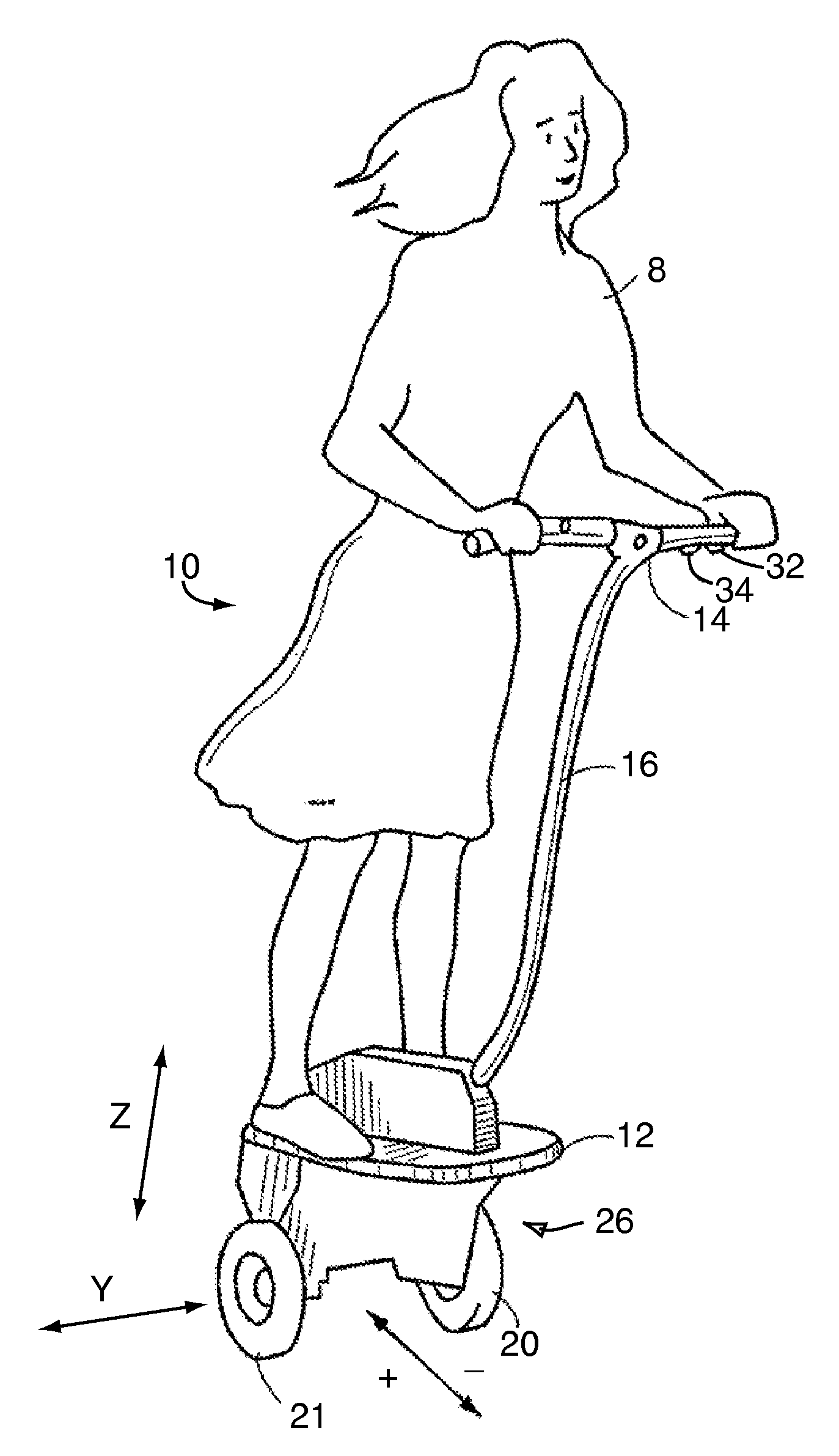
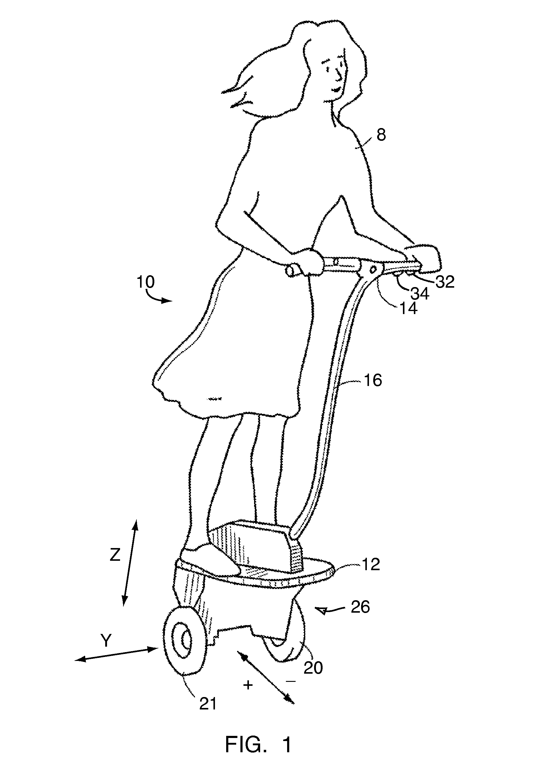
[0018]FIG. 1 shows a transporter, designated generally by numeral 10, of a sort to which the present invention may advantageously be applied. Transporter 10 is described in detail in U.S. Pat. No. 6,302,230, which is incorporated herein by reference in its entirety.

[0019]A characteristic of many transporter embodiments to which the present invention may be applied is the use of a pair of laterally disposed ground-contacting members 20 and 21 to suspend a subject 8 over a surface with respect to which the subject is being transported. The ground or other surface, such as a floor, over which a vehicle in accordance with the invention is employed may be referred to generally herein as the “ground.” The ground-contacting members 20, 21, here depicted as wheels, are typically motor-driven. In many embodiments, the configuration in which the subject is suspended during locomotion lacks inherent stability in the fore-aft plane at least a portion of the time with respect to a vertical (axis...


PUM


Abstract

A method for conducting the motion of a transporter under riderless conditions. The transporter has two laterally disposed primary wheels. In accordance with the method, an input is received via a user input disposed on the transporter and a control signal corresponding to the input received is generated. Then a torque is applied to the laterally disposed wheels so as propel the transporter on the basis of at least the control signal.The control signal may correspond to either a commanded torque or to a commanded transporter velocity. The torque may include coadded terms where the terms are, respectively, proportional to the control signal, to a counteracting artificial friction proportional to the common velocity of the wheels, and a term proportional to the differential rotation of the wheels to facilitate turning of the transporter.

Description

[0001]The present application is a continuation-in-part application of copending U.S. application Ser. No. 09 / 325,976, filed Jun. 4, 1999, which is a continuation in part of U.S. application Ser. No. 08 / 479,901, filed Jun. 7, 1995, now issued as U.S. Pat. No. 5,975,225, which is a continuation in part of U.S. application Ser. No. 08 / 384,705, filed Feb. 3, 1995, now issued as U.S. Pat. No. 5,971,091, which is a continuation in part of U.S. application Ser. No. 08 / 250,693, filed May 27, 1994, now issued as U.S. Pat. No. 5,701,965, which in turn is a continuation in part of U.S. application Ser. No. 08 / 021,789, filed Feb. 24, 1993, now abandoned, from which the present application claims priority.[0002]Additionally, the present application is a continuation-in-part of U.S. Ser. No. 10 / 308,888, filed Dec. 3, 2002, and claims priority through the latter application from U.S. Ser. Nos. 60 / 336,601, filed Dec. 5, 2001, and 60 / 347,800, filed Jan. 10, 2002.[0003]Finally, this application clai...

Claims


Application Information

Patent Timeline
Patent Type & Authority Patents(United States)
IPC IPC(8): B62D61/12A61G5/04A61G5/06A61G5/10A61G5/12A61G5/14B60K7/00B62D57/00B62K17/00
CPCB62D37/00B62K17/00B62D57/00B62D61/00B62K3/007B62D51/02A61G2005/085A61G2005/0891B60K7/00A61G5/085A61G5/0891B62K11/007B60L50/51Y02T10/70
Inventor KAMEN, DEAN L.AMSBURY, BURLFIELD, J. DOUGLASLANGENFELD, CHRISTOPHER C.MORRELL, JOHN B.POMPA, JONATHAN B.STEVENS, JON M.LUND, JEREMY B.
Owner DEKA PROD LLP
Why Eureka
Try Eureka