Peelable seal

a seal and peeling technology, applied in the field of containers, can solve the problems of increasing the peak peeling force, and reducing the peeling for

Inactive Publication Date: 2009-06-16
BAXTER INT INC +1
View PDF238 Cites 45 Cited by
  • Summary
  • Abstract
  • Description
  • Claims
  • Application Information

AI Technical Summary

Problems solved by technology

This increased peak peel force is detrimental to use of the multichambered container by making it more difficult to initiate peeling to open the container.
This is especially true for patients using the medical solutions who may be infirmed or elderly and unable to provide the force necessary to initiate peeling.
Moreover, the peak peel force is difficult to control, some containers remaining easy to initiate peeling in the peelable seal, while others becoming almost impossible to initiate by hand.

Method used


Image

  • Peelable seal
  • Peelable seal
  • Peelable seal

Examples


Embodiment Construction

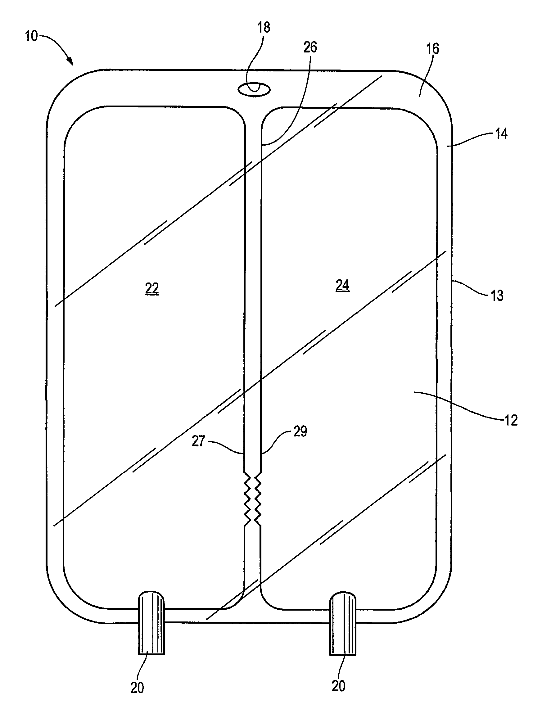
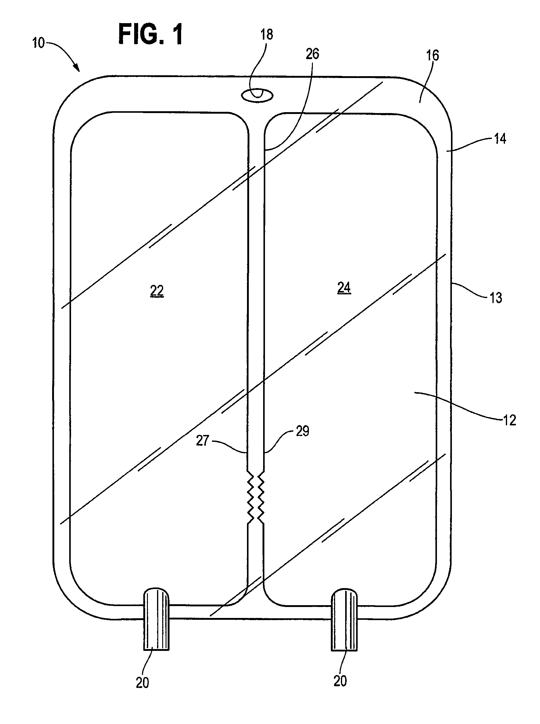
[0032]FIG. 1 shows an example of a chambered container 10 of the type used in connection with the present invention. The container 10 stores components that must be kept separate until mixed before administering them to a patient. The container 10 has a first sidewall 12 and a second sidewall 13 sealed along a common periphery 14. The peripheral seal 14 is preferably created by conductive heat sealing, but may be created by adhesive bonding, radio frequency sealing, thermal transfer welding, solvent bonding, ultrasonic or laser welding, or other suitable means.

[0033]The peripheral seal 14 may have an expanded portion 16 that includes a cutout 18 for hanging the container 10 from a hook or other means (not shown). The container 10 also includes one or more ports 20 from which the solution contained in the container 10 may be administered to a patient. The container 10 has two or more chambers 22 and 24 separated by a peelable seal 26. The container 10 of FIG. 1 has two chambers 22 an...


PUM


Abstract

The present invention provides a peelable seal for a multi-chambered container including a first edge and a second edge. At least one of the first edge or second edge includes a stress bearing portion and a non-stress bearing portion.

Description

[0001]The present application is a continuation of U.S. patent application Ser. No. 10 / 273.825 filed on Oct. 17. 2002 now U.S. Pat. No. 7,175,614, the content of which is expressly incorporated by reference.BACKGROUND OF THE INVENTION[0002]The present invention relates to a container for delivering fluids. In particular, it relates to a peelable seal between chambers of a multiple chambered container to separately store two or more components for administering to a patient. The components can be in a powder or liquid form and are typically mixed together to form a therapeutic solution. Such solutions can include intravenous solutions, nutritional solutions, drug solutions, enteral solutions, parenteral solutions, dialysis solutions, pharmacological agents including gene therapy and chemotherapy agents, and many other fluids that may be administered to a patient.[0003]Due to stability, compatibility, or other concerns, some medical solutions have to be stored separately prior to admi...

Claims


Application Information

Patent Timeline
Patent Type & Authority Patents(United States)
IPC IPC(8): B65D30/02A61B19/00A61J1/00A61J1/10A61J1/20B65D81/32
CPCA61J1/2093B65D81/3266A61J1/10A61J2001/2024A61J1/2024B65D81/32
Inventor GOLLIER, PAUL ANDREBALTEAU, PATRICKHOUWAERT, VINCENTPELUSO, FRANCESCO
Owner BAXTER INT INC
Why Eureka
Try Eureka