Positive contrast roadway lighting system

a technology of roadway lighting and positive contrast, which is applied in the direction of fixed installation, lighting and heating equipment, instruments, etc., can solve the problems of animal and pedestrian intrusion and other problems

Inactive Publication Date: 2009-06-16
WALKER CHRIS
View PDF6 Cites 14 Cited by
  • Summary
  • Abstract
  • Description
  • Claims
  • Application Information

AI Technical Summary

Benefits of technology

[0021]In another method for illuminating a roadway having traffic moving in a flow direction, a luminaire is mounted at an angle with respect to the roadway such that a greater portion of light emitted from the luminaire is directed in the traffic flow direction than is directed against the traffic flow direction. Light emitted from the luminaire is prevented from traveling against the traffic flow direction with a shield.

Problems solved by technology

This establishes limits on light emitted vertically from the luminaire to minimize “skyglow.” Skyglow is the result of light directed upward into the atmosphere and is an undesired effect of outdoor lighting.
However, this light distribution results in glare and alternating areas of positive (in the direction of traffic) and negative (against the direction of traffic) light contrast.
Slower traffic having mechanical problems typically travel to the right and animal and pedestrian intrusion also occurs in this area.

Method used


Image

  • Positive contrast roadway lighting system
  • Positive contrast roadway lighting system
  • Positive contrast roadway lighting system

Examples


Embodiment Construction

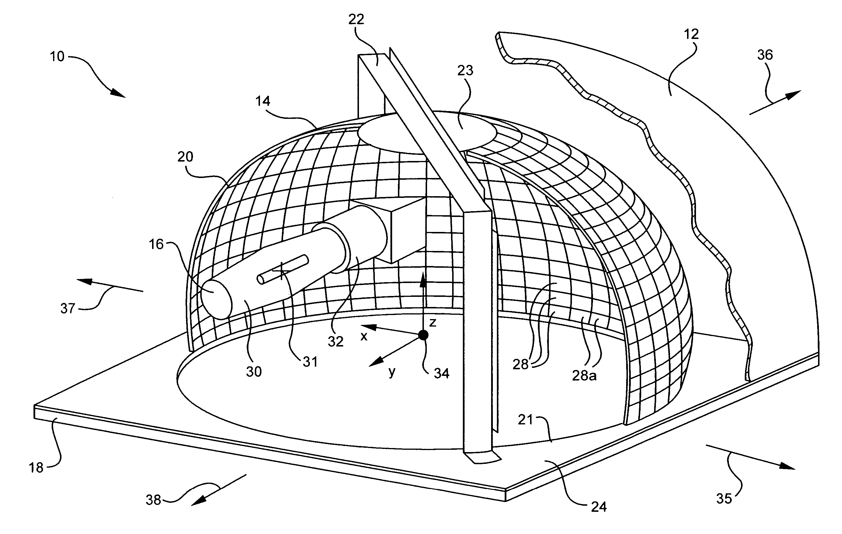
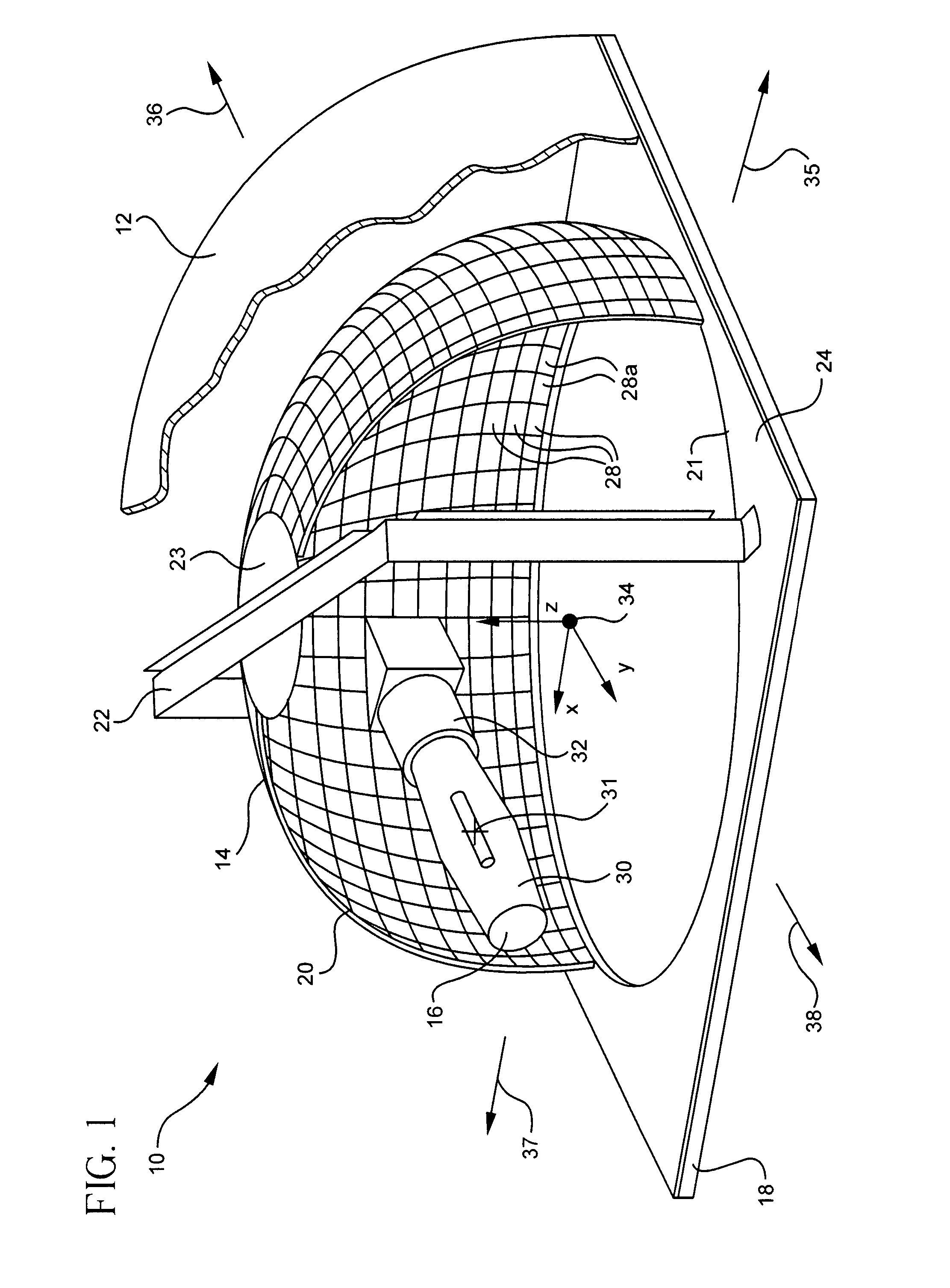
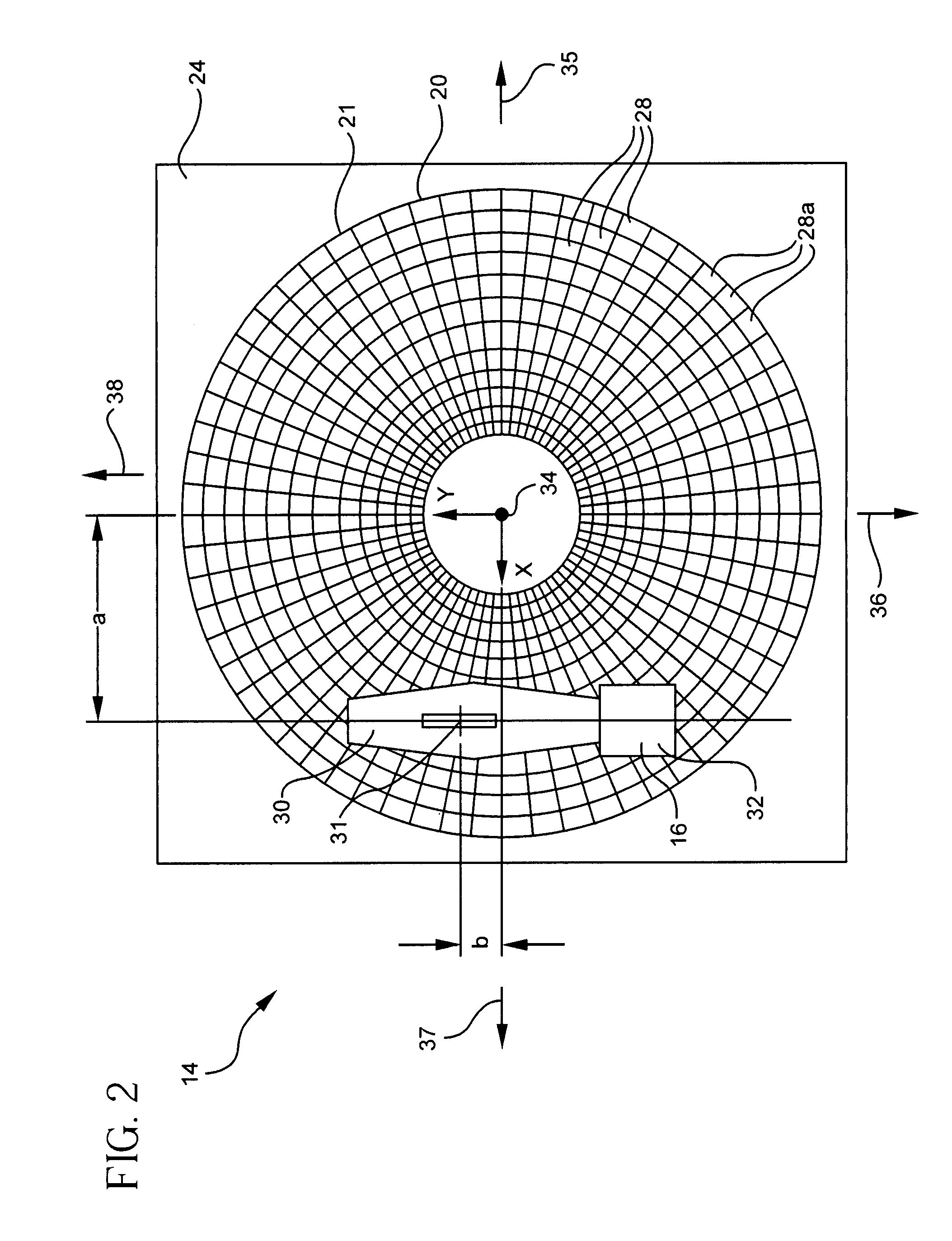
[0038]Referring first to FIGS. 1-3, a luminaire 10 according to the present invention is shown. The luminaire 10 generally includes a luminaire housing 12, a reflector 14, a lamp assembly 16 and a lens plate 18.

[0039]The luminaire housing 12 can be of any shape or configuration and is adapted to mount to a light pole (not shown). The housing is preferably made from a die cast aluminum and has a minimum wall thickness of 0.093″. In a preferred embodiment, the housing 12 has a “cobra-head” style since such is the most common style found in conventional roadway luminaires. In general, the light pole will be positioned offset from the side of a roadway, wherein light is distributed up the road in the direction of traffic 35, down the road in a direction against traffic 37, perpendicularly across the road in a “street side” direction 36 and back toward the pole in a “house side” direction 38.

[0040]The reflector 14 includes a radially symmetrical dome portion 20, a bracket portion 22 and ...


PUM


Abstract

A luminaire assembly generally includes a reflector having a center of symmetry and a lamp supported within the reflector, wherein the lamp is offset from the reflector center of symmetry, whereby light emitted from the lamp is reflected by the reflector in an asymmetric pattern. In a method of illuminating a roadway having traffic moving in a flow direction, a luminaire having a reflector and a lamp is mounted at a side of the roadway and light emitted from the lamp is reflected with the reflector whereby a greater portion of the reflected light is directed in the traffic flow direction than is directed against the traffic flow direction.

Description

CROSS-REFERENCE TO RELATED APPLICATIONS[0001]This application claims the benefit of U.S. Provisional Application No. 60 / 837,221, filed on Aug. 11, 2006.FIELD OF THE INVENTION[0002]The present invention relates to luminaires for outdoor lighting and, more particularly, to a positive contrast roadway luminaire and lighting system.BACKGROUND OF THE INVENTION[0003]There are two groups that make recommendations and set standards for the lighting of roadways in the United States. These are the Illumination Engineering Society of North America (IESNA) in conjunction with the American National Standard Institute (ANSI), which publishes the American National Standard Practice for Roadway Lighting designated ANSI / IESNA RP-8-2000, and the American Association of State Highway and Transportation Officials (AASHTO), which publishes the “Roadway Lighting Design Guide”. Moreover, the Federal Highway Administration (FHWA) has a manual for roadways, namely The Roadway Lighting Handbook 1978 (revised...

Claims


Application Information

Patent Timeline
Patent Type & Authority Patents(United States)
IPC IPC(8): F21S6/00
CPCF21V7/04F21V7/09F21W2131/103F21S8/085
Inventor WALKER, CHRISBILSON, EDWARD B.KAUFFMAN, RICK W.
Owner WALKER CHRIS
Why Eureka
Try Eureka