Magnetic sensor system

a sensor and magnetic field technology, applied in the field of magnetic sensor systems, can solve the problems of inability to carry out, reduce use of magnets, etc., and achieve the effect of reducing the sensitivity of the sensor to homogeneous interference fields, and reducing the sensitivity of the sensor

Inactive Publication Date: 2009-06-16
ROBERT BOSCH GMBH
View PDF8 Cites 18 Cited by
  • Summary
  • Abstract
  • Description
  • Claims
  • Application Information

AI Technical Summary

Benefits of technology

[0009]With the present invention, therefore, the design of a magnetic circuit that produces a working field for a sensor that operates using the gradiometer principle, i.e., by detecting a field gradient, is optimized and therefore enables offset-free operation of the sensor when the magnetic field is varied by mobile transmitter elements, in particular toothed wheels. To this end, the magnetic circuit was created using two individual magnets, the fields of which overlap such that the “in-plane” components of the resultant magnetic field at the gradiometer positions are reduced to the extent that they vary around the zero position due to the influence of the passive transmitter elements. As a result, very small signals can be detected without offset.
[0011]With an advantageous embodiment, homogenization plates are located between the sensor elements and the permanent magnets. The field is therefore homogenized in the plane of the sensor elements, and the level of positioning accuracy required of the sensor elements relative to the pair of magnets for offset-free operation is reduced.
[0012]It is also advantageous when, according to a further embodiment, the magnetization of each of the permanent magnets is rotated by a specified angle α relative to their longitudinal direction facing the sensor elements.

Problems solved by technology

Unlike the use of XMR elements, which perform absolute measurements, the application of the gradiometer principle in a magnetoresistive XMR measurement bridge results in a reduction of the sensitivity of the sensors to homogeneous interference fields.
An alignment of the magnets used previously, which was carried out so that the offset can be eliminated at both locations of the sensor elements of the gradiometer system, cannot be carried out in this case, however; although electronic alignment is possible, in principle, a relatively small signal is obtained here with a large offset.

Method used


Image

  • Magnetic sensor system
  • Magnetic sensor system
  • Magnetic sensor system

Examples


Embodiment Construction

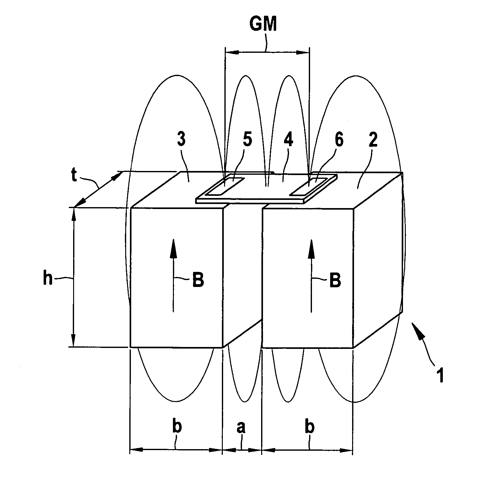
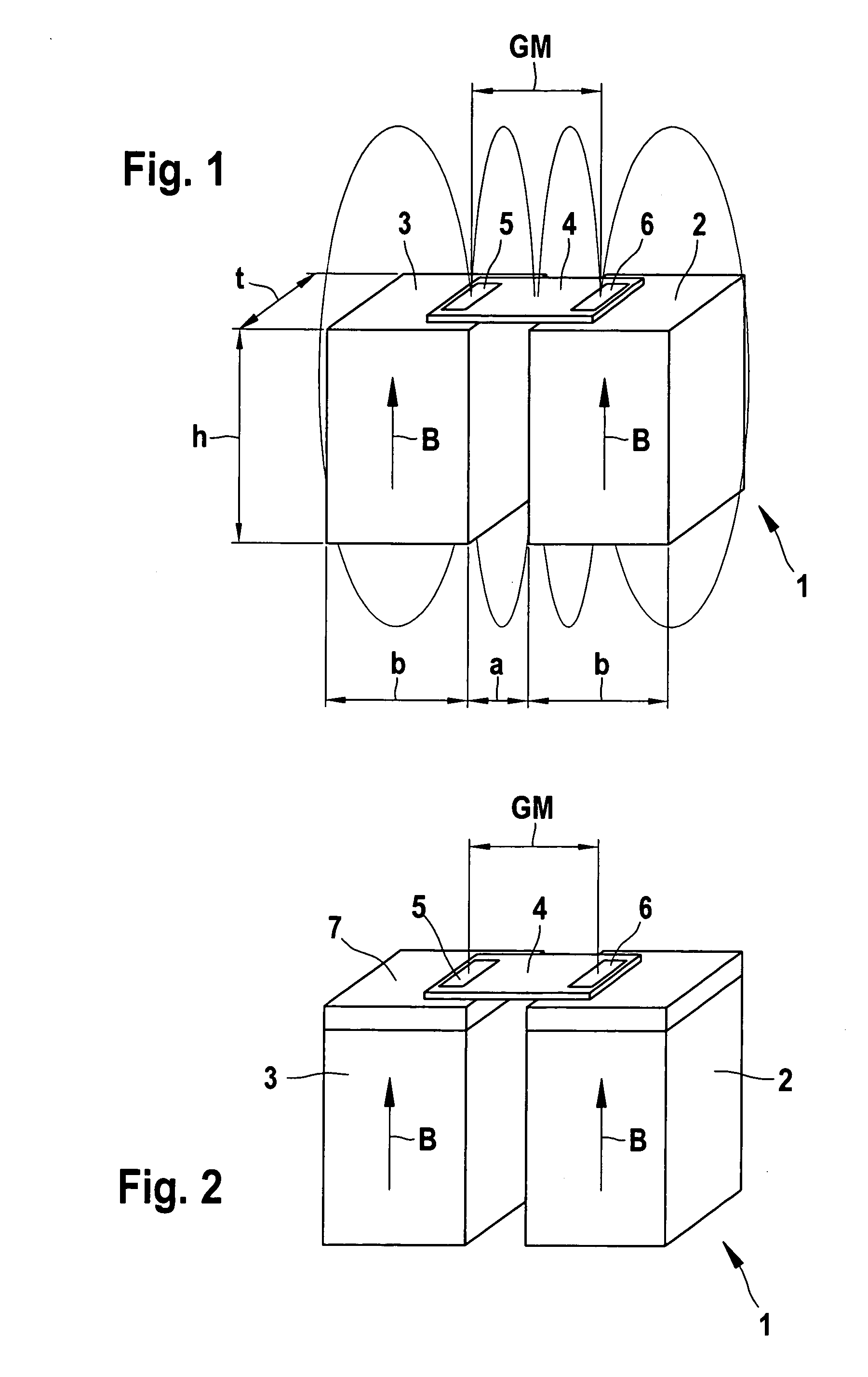
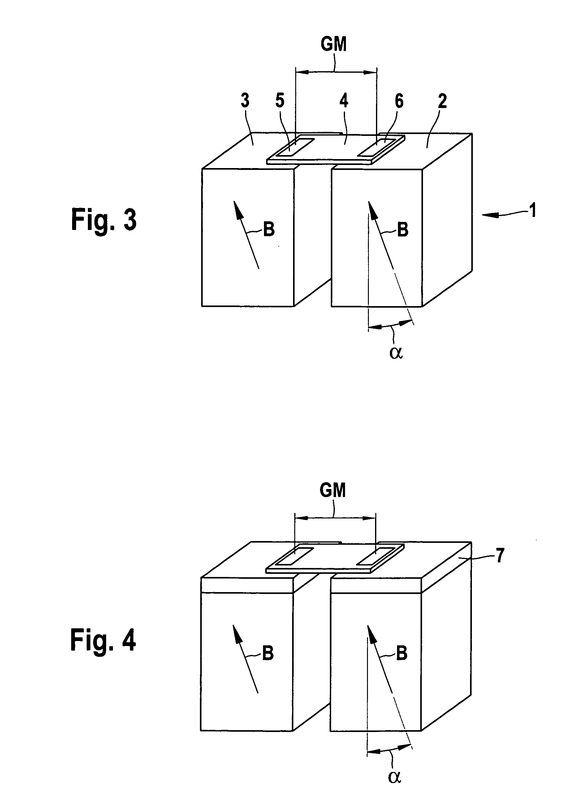
[0022]FIG. 1 shows a schematic illustration of a magnetic sensor system 1 that includes two permanent magnets 2 and 3, the respective magnetic fields B of which are oriented with lines of flux shown in this illustration in the direction toward a sensor 4. In this case, sensor 4 is designed as an XMR sensor and has two magnetoresistive sensor elements 5 and 6. Sensor elements 5 and 6 are shown in a gradiometer system with gradiometer separation GM; they detect the changes in the particular field gradient caused, e.g., by 5 a metallic transmitter element, e.g., a toothed wheel shown in FIG. 5, that passes by magnetic sensor system 1.

[0023]The optimum working point of sensor 4 is adjusted via distance a between magnets 2 and 3 and can be adapted to the gradiometer separation GM of sensor elements 5 and 6. Furthermore, the courses of the lines of flux depend on the dimensions h, b and t of permanent magnets 2 and 3. Given a fixed gradiometer separation GM, e.g., 2.5 mm, the size, materi...


PUM


Abstract

A magnetic sensor system (1) is provided that contains sensor elements (5, 6) that are sensitive to magnetic fields, the electrical properties of said sensor elements being modifiable according to a magnetic field that can be influenced by a mobile, passive transmitter element (8). The magnetic sensor system (1) includes two sensor elements (5, 6) in a gradiometer system, each of which is assigned to one of two permanent magnets (2, 3) having a predetermined separation. In terms of their dimensions, separation and position relative to the sensor elements (5, 6), the permanent magnets (2, 3) are located such that the offset of the output signal of the sensor elements (5, 6) is minimized in the gradiometer system.

Description

CROSS-REFERENCE[0001]The invention described and claimed hereinbelow is also described in PCT / EP 2005 / 050063, filed on Jan. 7, 2005 and DE 102004011809.4, filed Mar. 11, 2004. This German Patent Application, whose subject matter is incorporated here by reference, provides the basis for a claim of priority of invention under 35 U.S.C. 119 (a)-(d).BACKGROUND OF THE INVENTION[0002]The present invention relates to a magnetic sensor system, in particular for sensing the motion of elements moved in a linear or rotary manner.[0003]It is known per se that sensors that are sensitive to magnetic fields are used in many applications where contactless detection of motion is desired. The motion can be rotary or linear. A distinction must be made here between two fundamentally different measurement principles. In one case, one or more magnetic dipoles are mounted, as the active elements, on the element to be detected, and the motion is determined directly via the magnetic field, which changes wit...

Claims


Application Information

Patent Timeline
Patent Type & Authority Patents(United States)
IPC IPC(8): G01R33/02G01R33/09G01D5/14G01P3/42G01P3/487G01R33/022
CPCG01D5/147G01P3/487G01R33/022
Inventor HERRMANN, INGOFARBER, PAULMAY, ULRICHBAUER, CHRISTIANVOGELGESANG, BIRGIT
Owner ROBERT BOSCH GMBH
Why Eureka
Try Eureka