Method of reverse link dynamic power control in a wireless communication system using quality feedback from a delay-sensitive traffic stream or overhead channel

a technology of dynamic power control and reverse link, applied in power management, instruments, coding, etc., can solve the problems of complex inner and outer control loops, not really effective and efficient systems, and the above-described prior art mechanism is complicated and not really effective and efficient, so as to achieve the effect of reducing the interference between cdma and ic, reducing the interference between ats whose rl signals are decoded earlier, and improving the efficiency

Inactive Publication Date: 2009-06-16
ALCATEL-LUCENT USA INC
View PDF8 Cites 24 Cited by
  • Summary
  • Abstract
  • Description
  • Claims
  • Application Information

AI Technical Summary

Benefits of technology

[0010]Embodiments of the present invention use a closed-loop dynamic power control that is based on receiving a quality feedback. As a result, the inner loop power control used by the prior art is removed. In addition the dedicated power control channel and power control bits are also eliminated. Further, the complicated RNC / BTS-based outer loop power control is also removed. Advantageously, embodiments that employ this closed-loop dynamic power control have significantly reduced overhead and complexity compared to the existing prior art power control mechanisms.

Problems solved by technology

The above-described prior art mechanism involving inner and outer control loops is complicated and not really effective and efficient for systems with multi-flow applications including conversational streaming and burst types of traffic.
On the other hand, however, in a CDMA system with IC, the ATs whose RL signals are decoded earlier will still be impacted more by the intra-cell interference.
Further, there is still inter-cell interference for both CDMA with IC and OFDMA systems.
In addition, in a new RevC system, inter-cell interference is also an important factor that needs to be considered for power control.

Method used


Image

  • Method of reverse link dynamic power control in a wireless communication system using quality feedback from a delay-sensitive traffic stream or overhead channel
  • Method of reverse link dynamic power control in a wireless communication system using quality feedback from a delay-sensitive traffic stream or overhead channel
  • Method of reverse link dynamic power control in a wireless communication system using quality feedback from a delay-sensitive traffic stream or overhead channel

Examples


Embodiment Construction

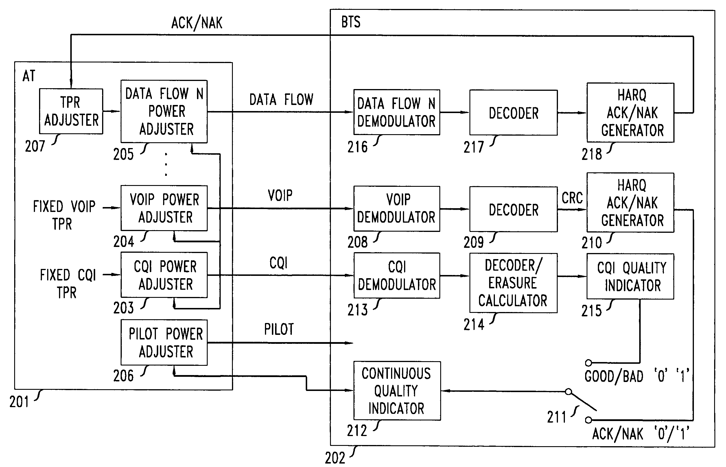
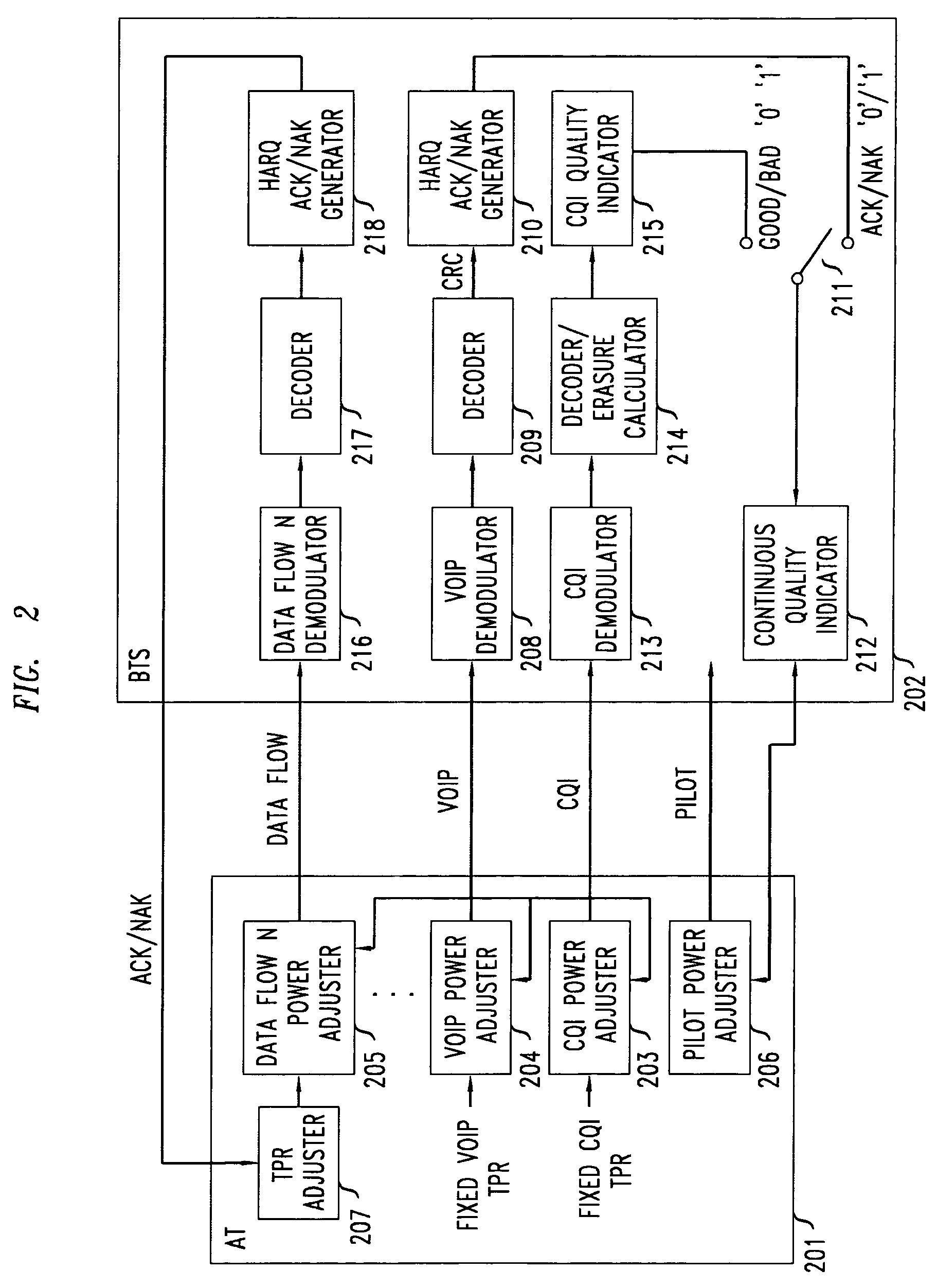
[0022]With reference to FIG. 2, the architecture of a closed loop dynamic power control that is based solely on the feedback of a quality measure is shown. The architecture includes a dynamic power control of the main reference pilot being transmitted by AT 201 that is based on the feedback from the BTS 202 of a continuous quality indication that is derived from the quality of a substantially continuously BTS-received delay-sensitive traffic stream that is transmitted on the RL. Specifically, in this embodiment, the continuous quality indication is the HARQ ACKs / NAKs fed back to AT 201 that are generated at BTS 202 in response to received, demodulated, and decoded packets of VoIP speech data. When a delay-sensitive traffic stream is not being transmitted by AT 201 (and thus not being received by BTS 202), a quality metric derived at the BTS 202 from a continuously received RL overhead channel is fed back to the AT 201 to control the pilot power. Specifically, in this embodiment, “go...


PUM


Abstract

A closed loop power control based on receiving a continuous quality feedback is described. A main reverse link (RL) pilot is controlled by the quality feedback of a substantially continuous delay-sensitive traffic stream, such as Voice-over-IP (VoIP), when such a stream is enabled. When such a stream is not enabled, the quality of a continuous RL overhead channel is used to control the pilot power. At the same time, the Traffic-to-Pilot Ratios (TPR) of contemporaneously transmitted delay-sensitive data streams are independently adjusted based on a quality feedback associated with each such data stream.

Description

CROSS REFERENCE TO RELATED APPLICATIONS[0001]This application describes and claims subject matter that is also described in co-pending United States patent applications filed simultaneously herewith and entitled Method of Reverse Link Dynamic Power Control in a Wireless Communication System Using Per-Flow Quality Feedback for Multi-Flow Data Traffic, Ser. No. 11 / 331,994.TECHNICAL FIELD[0002]This invention relates to wireless communications.BACKGROUND OF THE INVENTION[0003]In conventional CDMA systems, intra-cell interference contributes to the major portion of the total interference in the Reverse Link (RL). Tight (fast) RL power control with dedicated power-control sub-channels are required to ensure a proper signal-to-noise (SNR) level of a mobile terminal and to minimize its interference to other users due to the well-known near-far problem.[0004]In currently existing 3G CDMA systems, in order to minimize intra-cell interference, the fundamental power control (PC) mechanism invol...

Claims


Application Information

Patent Timeline
Patent Type & Authority Patents(United States)
IPC IPC(8): H04B7/00H04J13/00H04W52/08H04W52/14H04W52/24H04W52/28H04W52/32
CPCH04W52/08H04W52/146H04W52/325H04W52/286H04W52/24H04B7/005
Inventor VASUDEVAN, SUBRAMANIANZOU, JIALIN
Owner ALCATEL-LUCENT USA INC
Why Eureka
Try Eureka