Protective enclosure

a protective enclosure and protective technology, applied in the field of chemical protective enclosures, can solve the problems of increasing the residence time of the agent in the chemical protective material, and achieve the effect of high protection

Inactive Publication Date: 2009-06-23
WL GORE & ASSOC INC
View PDF26 Cites 22 Cited by
  • Summary
  • Abstract
  • Description
  • Claims
  • Application Information

AI Technical Summary

Benefits of technology

[0007]In the present invention protective enclosures are provided that are sealed from chemical or biological hazardous threats while having sufficient air and carbon dioxide permeability to sustain the life of the occupants without the use of an auxilliary air source, such as the heavy, powered, bulky filtration units currently used to achieve high levels of protection. Surprisingly, no external air supply and no internal air purification units are needed to maintain a life-supporting internal atmosphere. Preferred protective enclosures of the present invention have a waterproof outer surface, where one portion of the enclosure's outer surface is a barrier section that is impermeable to liquids and gases, and another portion of the outer surface is air diffusive. The air diffusive portion restricts the passage of bulk air, thereby substantially inhibiting the ingress of toxic chemical agents, while permitting adequate diffusion of air into the protective enclosure to sustain life. A chemical protective material is provided adjacent to the air diffusive section to eliminate any remaining chemical or biological threat that may pass through the air diffusive section.
[0008]Protective enclosures of the present invention further provided protection against wind driven agent challenges. When transporting an injured person in a casualty bag into a transport helicopter, the rotor wash during a hover can range from 9 to 15 m / s for military aircraft which equates to air pressures between about 50 Pa to about 135 Pa. (Reference: Teske, M. E., et. al., Field Measurements of Helicopter Rotor Wash in Hover and Forward Flight, 2nd International Aeromechanics Specialists' Conference, American Helicopter Society, Bridgeport, Conn., 1995.) Thus, the preferred protective enclosure of the present invention blocks convective air flow at higher air pressures, and optimally reduces the ingress of chemical or biological agent challenges to a diffusive mechanism. Blocking convective airflow through the protective barrier increases the opportunity of a chemical assault to be reduced by evaporation or transmission away from the outside surface of the enclosure. Moreover, the ingress of any remaining chemical or biological agent by way of diffusion results in an increase in the residence time of the agent in the chemical protective material. By increasing the residence time of the penetrant as it begins to diffuse into the protective enclosure, a much thinner and lighter layer of the chemical protective material (16) is required to stop passage of agent through to the internal environment of the enclosure. Absent the novel diffusive characteristics of the protective enclosures of the present invention, much thicker layers of chemical protective material would be required to accommodate the shorter residence time of convectively flowing penetrants.

Problems solved by technology

Moreover, the ingress of any remaining chemical or biological agent by way of diffusion results in an increase in the residence time of the agent in the chemical protective material.

Method used


Image

  • Protective enclosure
  • Protective enclosure
  • Protective enclosure

Examples


example 1

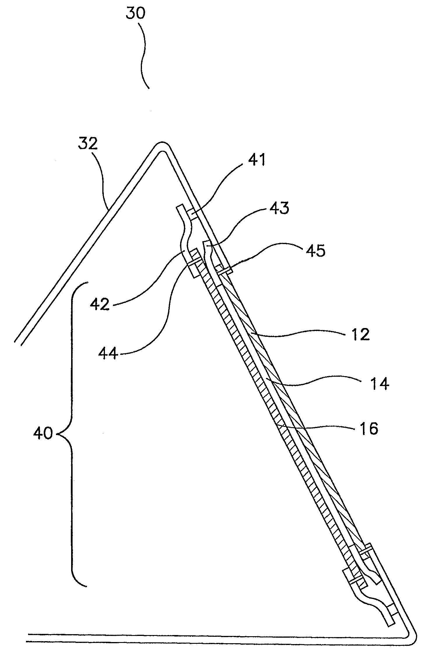
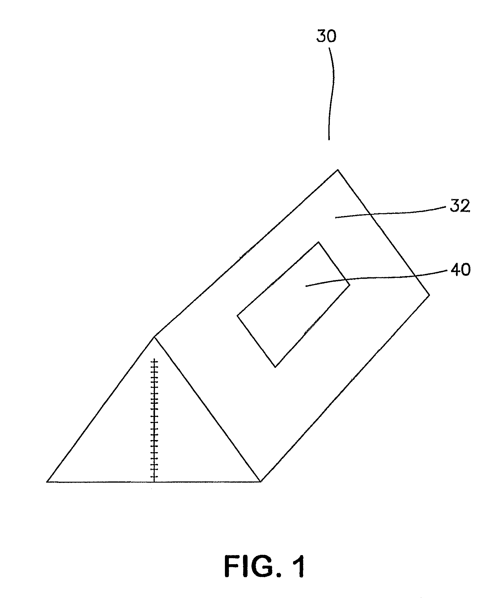
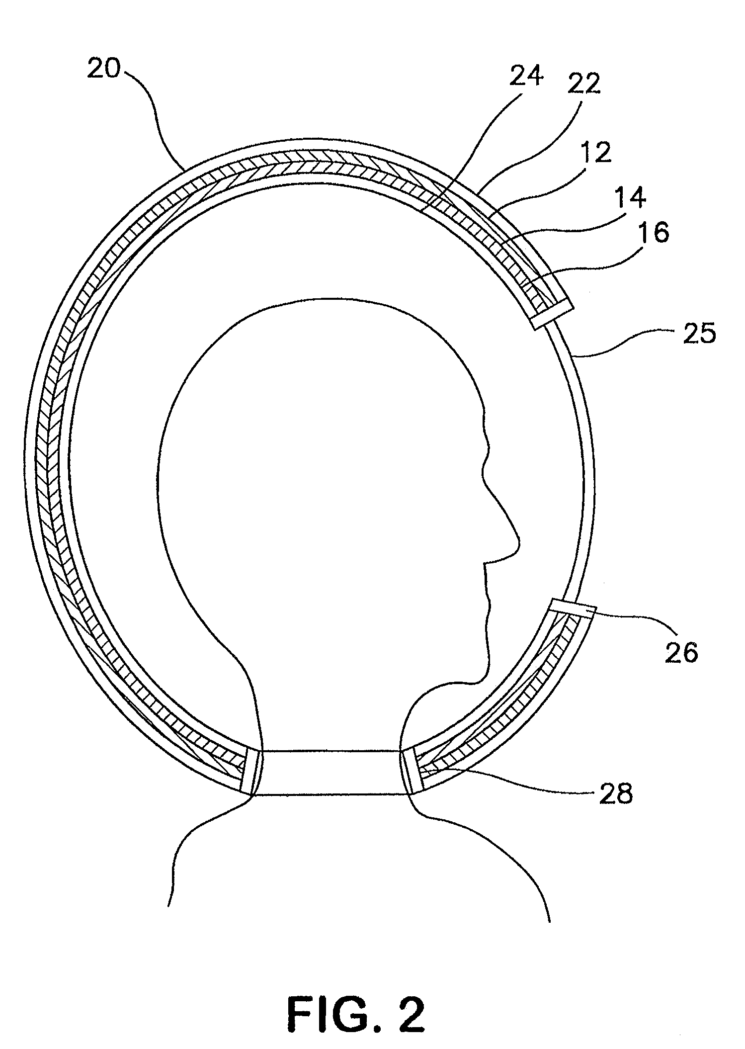
[0051]A preferred embodiment comprising the diffusive protective panel of the present invention was constructed comprising an air diffusive portion and a chemical protective material. Experiments were conducted to determine the number of layers and the weight of carbon required to provide a desired level of protection from permeation of chemical agents through the material. The chemical protective material (16) samples of this example were prepared based on activated carbon. A swatch of material containing activated carbon beads was cut from the liner of a Saratoga® suit (Texplorer® GmbH, Nettetal, Germany). The approximate areal density of carbon in the liner according to the literature was 180 g / m2. In an attempt to independently confirm this areal density, the liner was carefully deconstructed, and the beads mechanically removed. The measured carbon areal density was about 180-200 g / m2. Samples of carbon hereafter referred to as ‘carbon layer A’, were cut from the liner material ...

example 2

[0063]In this example, the constructions of Example 1 were tested against HD and Sarin (GB) chemical warfare agents. Vapor challenges at 40 mg / m3 and 1000 mg / m3, respectively, held continuously, were tested using swatch testing in a dual flow configuration according to TOP 8-2-501, as described previously. Constructions consisting of either one or three layers of ‘carbon layer A’ in combination with ‘face textile B’ were subjected to the HD or GB vapor challenge. The data from these tests were then used to determine the total cumulative breakthrough measured in μg / cm2 at 20 hours as shown in Table 3.

[0064]The time required for a person to have a 50 percent chance of either death (LCt50) or permanent damage (ECt50), was calculated from the total cumulative breakthrough values in Table 3. An explanation of these calculations is given in “Review of Acute Human Toxicity Estimates for Selected Chemical Warfare Agents.”

[0065]To convert the breakthrough values to a concentration*time value...

example 3

[0072]The liquid-proof characteristic of this invention was determined using the Suter test method described above. Because the chemical protective material of each embodiment was not expected to be waterproof, the suter testing was conducted on the face textiles “A” and “B” described above. Embodiments constructed with face textile B all did not leak after 3 minutes at 1 psi water pressure. In contrast, all embodiments constructed with face textile A leaked as soon as the water pressure began to register on the pressure gauge.


PUM

PropertyMeasurementUnit
pressureaaaaaaaaaa
thicknessaaaaaaaaaa
air pressuresaaaaaaaaaa

Abstract

The present invention describes chemical protective enclosure comprising a waterproof outer surface comprising an impermeable portion and an air diffusive portion, and further comprising a chemically adsorptive material substantially adjacent the air diffusive portion, wherein there is sufficient diffusion of breathable air into the chemical protective enclosure to sustain life.

Description

FIELD OF THE INVENTION[0001]The present invention relates to a chemical protective enclosure that is impermeable to liquids while having sufficient air permeability to sustain life.BACKGROUND OF THE INVENTION[0002]Various masks, coverings, garments and shelters are known for providing protection against contaminants, such as hazardous chemical and biological agents. Gas masks provide some protection by filtration means, however, the benefits of a mask are limited, among other things, by difficulty in obtaining proper fit and lack of skin protection. Chemically resistant materials are known for use in protective garments and the like to provide protection from direct skin contact. For example, air permeable protective garments made of adsorbent filter material affixed to air permeable textile supports are disclosed in U.S. Pat. Nos. 4,510,193, and 4,153,745. Materials permeable to both water vapor and air advantageously provide enhanced wearer comfort, and such garments may be used i...

Claims


Application Information

Patent Timeline
Patent Type & Authority Patents(United States)
IPC IPC(8): E04H15/54A62B17/00
CPCA62B31/00Y10T428/2481Y10T428/24998
Inventor FARNWORTH, BRIANGUNZEL, EDWARD C.CULLER, GREGORY D.
Owner WL GORE & ASSOC INC
Why Eureka
Try Eureka