Cooling panel for a furnace for producing iron or steel

a technology of iron or steel and cooling panel, which is applied in the direction of laminated elements, heating types, lighting and heating apparatus, etc., can solve the problems of inability to achieve far, and achieve the effect of reducing pressure loss, avoiding discontinuities in flow patterns, and pre-determined pressure losses in individual cooling circuits

Inactive Publication Date: 2009-06-23
PAUL WURTH SA
View PDF17 Cites 16 Cited by
  • Summary
  • Abstract
  • Description
  • Claims
  • Application Information

AI Technical Summary

Benefits of technology

This patented design allows for easier control over how fluid flows through different parts within a heat exchanger system without causing any issues such as pressure drop caused by differences in temperature across certain areas along its length. Additionally, this design simplifies manufacturing processes while maintaining precise dimensions and ensures proper alignment during installation. Overall, it improves efficiency and performance of the overall heat exchange system.

Problems solved by technology

The technical problem addressed in this patent text is the need for improved cooling plates for metallurgical furnaces, particularly in the case of copper cooling plates. The current methods for manufacturing copper cooling plates, such as mould casting and continuous casting, have limitations such as cavities and porosity, which negatively impact the life and thermal conductivity of the plates. Additionally, the current methods require expensive and time-consuming processes. The patent text proposes a new method for manufacturing copper cooling plates that overcomes these limitations and provides improved cooling performance.

Method used


Image

  • Cooling panel for a furnace for producing iron or steel
  • Cooling panel for a furnace for producing iron or steel
  • Cooling panel for a furnace for producing iron or steel

Examples


Embodiment Construction

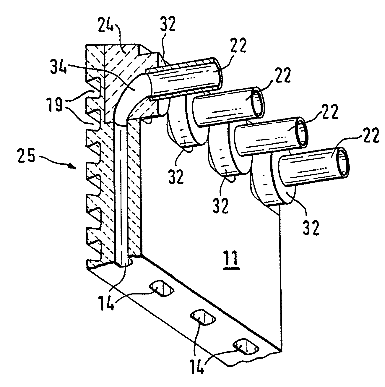
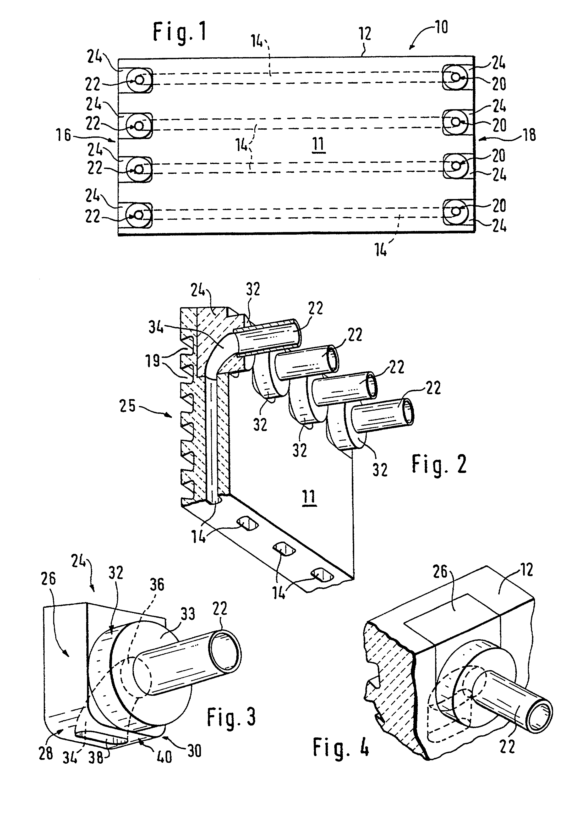
[0030]FIG. 1 shows a cooling plate 10 for a shaft furnace, in particular a blast furnace. Such cooling plates, also known as “staves”, are arranged on the inside of the furnace shell and connected to the furnace cooling system. The back 11 of the cooling plate 10 shown in FIG. 1 is opposite the furnace shell.

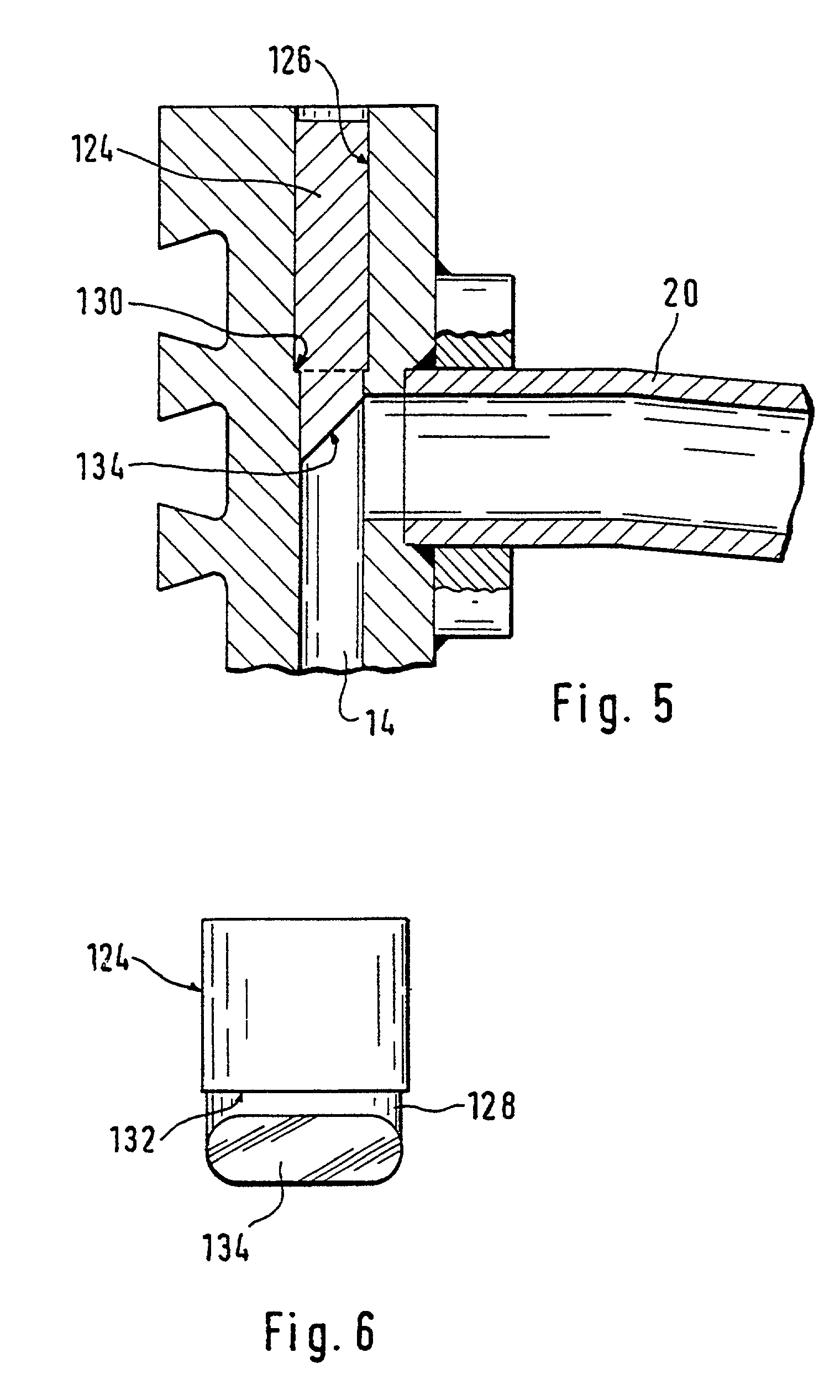
[0031]The cooling plate 10 shown consists essentially of a cooling plate body 12 made from copper or a copper alloy with a rectangular surface. Four straight cooling ducts 14, which extend parallel with the surface through the cooling plate body 12 from one end 16 to the opposite end 18 are integrated in the cooling plate body 12. This cooling plate body 12 was advantageously manufactured by the method described in the subsequently published patent application WO 98 / 30345. A preform of the cooling plate body 12 was continuously cast in a continuous casting mould, whereby rod-type inserts in the casting duct produced ducts running in the casting direction, which form the cooling ...


PUM

PropertyMeasurementUnit
Thicknessaaaaaaaaaa
Shapeaaaaaaaaaa

Abstract

A cooling plate for an iron and steelmaking furnace includes a copper cooling plate body having at least one cooling duct for a cooling medium extending essentially parallel with the back of the cooling plate body. The cooling plate body further includes a preformed, externally accessible recess into which the cooling duct opens. A connection piece is utilized as a cooling medium connection on the back of the cooling plate body, while a formed piece fitted within the externally accessible recess forms a deflection surface for the cooling medium flowing from the connection piece into the cooling duct, or from the cooling duct into the connection piece.

Description


Claims


Application Information

Patent Timeline
Owner PAUL WURTH SA
Why Eureka
Try Eureka