
Method and apparatus for improving flow and pressure estimation in CPAP systems

a flow and pressure estimation and flow technology, applied in medical devices, life-saving devices, other medical devices, etc., can solve the problems of significant discrepancy and prior art cpap devices that exist in the background

Active Publication Date: 2016-12-27
RESMED LTD
View PDF42 Cites 1 Cited by
  • Summary
  • Abstract
  • Description
  • Claims
  • Application Information

AI Technical Summary

Benefits of technology

[0023]In the case of higher frequency changes such as during forced oscillation (˜4 Hz) this model models the pressure loss much more accurately.
[0031]In accordance with one aspect of the invention there is provided a method and apparatus for improving the determination of mask pressure based upon the estimation of pressure at the flow generator of a CPAP device.
[0032]In accordance with another aspect of the invention there is provided a CPAP apparatus for treatment of sleep disordered breathing that reduces pressure during exhalation from a first level accurately to a second level so as to maintain the swing between preset limits.
[0034]In another aspect of the invention, the first pressure level is determined in accordance with an automatic algorithm in which the derivative of flow is calculated at runtime, clipped to not go negative, and is bounded above by a predetermined value. The purpose of the bound is to avoid some detrimental effects of leaks in the mask.

Problems solved by technology

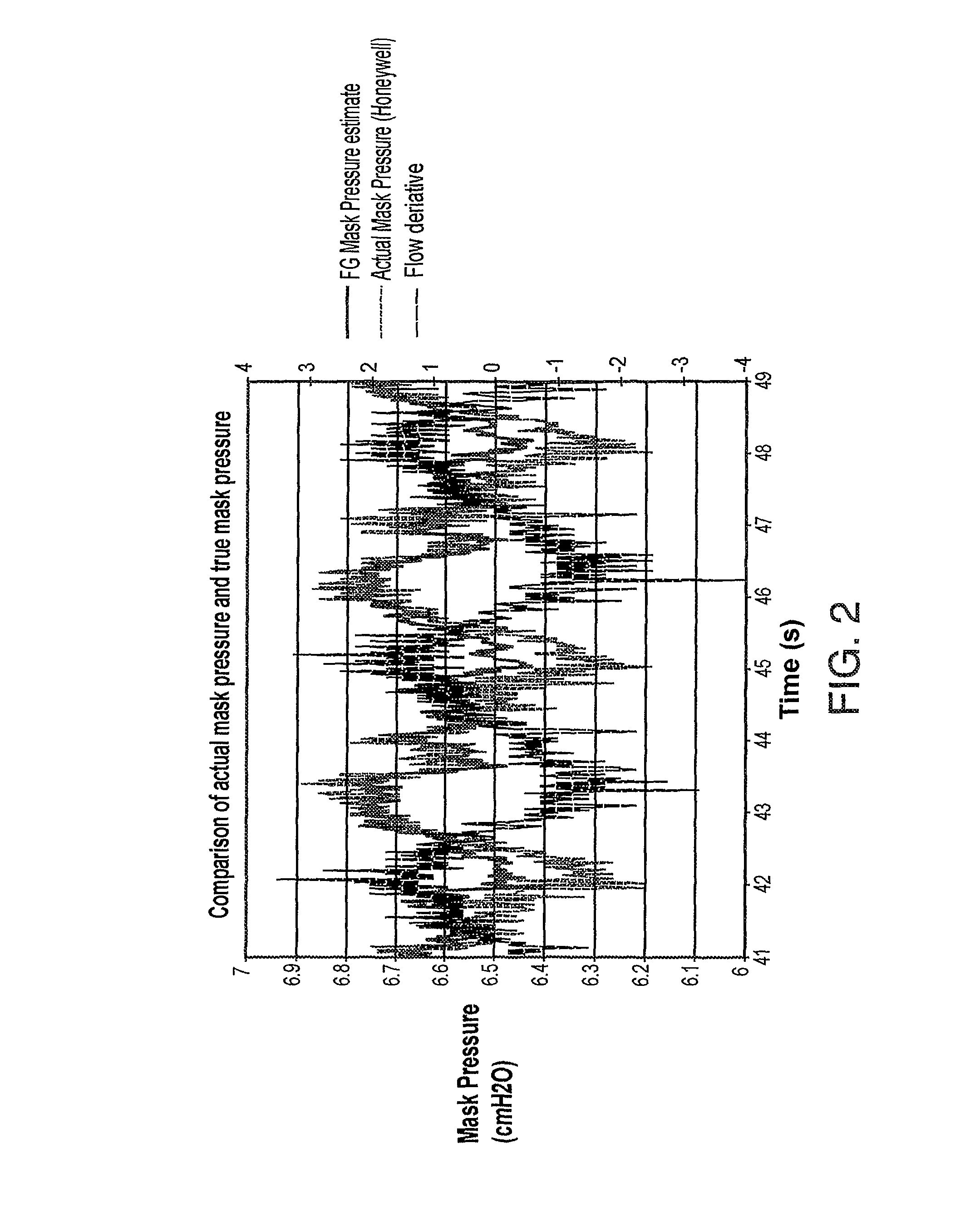
It has been determined that a discrepancy exists with prior art CPAP devices between the estimation of the mask pressure based upon measurements of flow and pressure at or near the location of the flow generator and the true mask pressure as accurately measured at the mask using a quality pressure transducer.
This discrepancy is significant during changes in the mask pressure and flow which can be caused by patient breathing and forced oscillation.

Method used


Image

  • Method and apparatus for improving flow and pressure estimation in CPAP systems
  • Method and apparatus for improving flow and pressure estimation in CPAP systems
  • Method and apparatus for improving flow and pressure estimation in CPAP systems

Examples


Embodiment Construction

[0041]A. Description of a Typical Apparatus

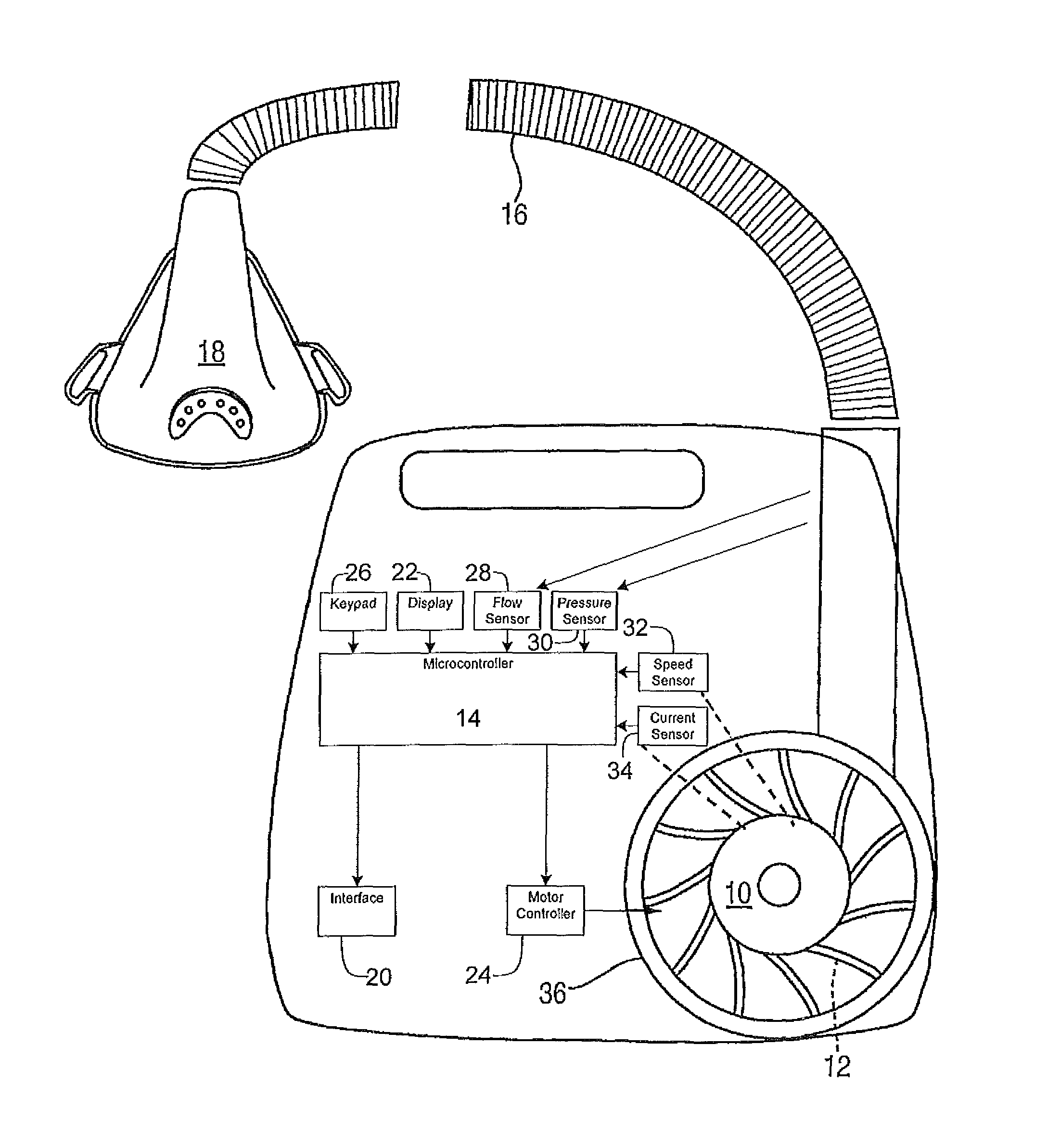
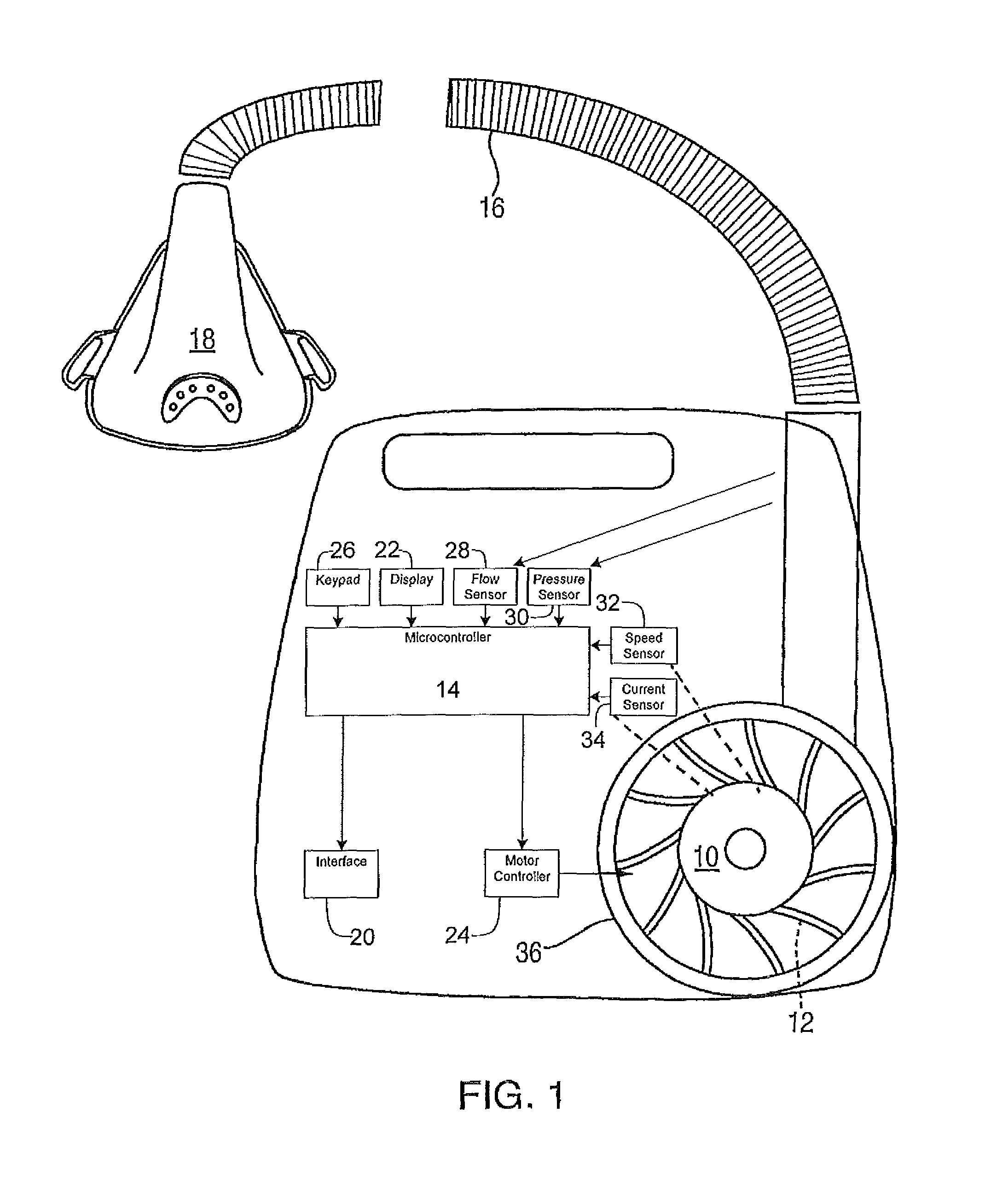
[0042]FIG. 1 shows apparatus in accordance with an embodiment of the invention. A brushless electric motor 10 has an impeller 12 attached to it. The impeller 12 resides in a volute 36. The motor 10 is under the control of a motor controller 24 (suitable controllers include TMS320LC2402 or MC33035 ICs). The motor includes sensors 32, 34 that provide signals indicative of motor rotational speed and current, respectively. When the windings of the motor are energized, the impeller rotates. Air is drawn in through the inlet of the impeller and gains momentum. As the air passes out of the impeller and into the volute, it changes speed and develops pressure. Air passes out of the volute, past flow and pressure sensors 28, 30 (such as SMI5652-003 flow sensor and SMI5652-008 or MPX2010 pressure sensors) respectively to an air delivery conduit 16 (for example, manufactured by Smooth-bore Plastics) that is in turn connected to a patient interface 18 w...


PUM


Abstract

A CPAP apparatus in which the swing in pressure at the patient interface is adjusted by regulating the air flow from the flow generator through an air delivery conduit taking into account a pressure drop representative of the inertance of the airflow in the air delivery conduit during the increase of air flow from the flow generator.

Description

I. FIELD OF THE INVENTION[0001]This invention relates to a method and apparatus for delivering a supply of air at positive pressure to a patient for treating sleep disordered breathing. The invention relates to a method of improved model accuracy of the patient circuit. In one case, the invention relates to a method and apparatus which provides improved accuracy of the delivered pressures throughout a breathing cycle. Another case of the inventions application is in the use of an algorithm that determines open and closed apneas. This invention is applicable to all algorithms that must estimate the dynamic characteristics of the patient circuit.II. BACKGROUND OF THE INVENTION[0002]A. Summary of Positive Pressure CPAP Machines[0003]Since the invention of nasal Continuous Positive Airway Pressure (nasal CPAP) for treatment of Obstructive Sleep Apnea (OSA) and other forms of Sleep Disordered Breathing (SDB) by Sullivan, as taught in U.S. Pat. No. 4,944,310, much effort has been directed...

Claims


Application Information

Patent Timeline
Patent Type & Authority Patents(United States)
IPC IPC(8): A61M16/00
CPCA61M16/00A61M16/0069A61M16/0066A61M2016/0027A61M2016/0036A61M16/024A61M16/0003A61M16/06A61M2016/003A61M2205/3334A61M2205/502
Inventor GOELDI, BENRIAH
Owner RESMED LTD
Learn More