Method for calibrating the orientation of a camera mounted to a vehicle

a technology for calibrating the orientation of a camera and a vehicle, which is applied in the direction of image analysis, image enhancement, instruments, etc., can solve the problems of time-consuming and therefore costly calibration, and the difficulty of placing the camera with a well-defined orientation relative to the vehicle, so as to prevent random errors in determining the vanishing point, the most easily or most reliably identified, and the determination is improved.

Active Publication Date: 2018-12-13
APTIV TECH LTD
View PDF4 Cites 21 Cited by
  • Summary
  • Abstract
  • Description
  • Claims
  • Application Information

AI Technical Summary

Benefits of technology

[0036]For an improved determination of the horizontal and/or vertical vanishing point, according to a preferred embodiment, the calibration pattern defines more than two horizontal lines and/or more than two vertical lines. Then, it is possible to choose representations of those two horizontal and/or vertical lines for determining the horizontal or vertical vanishing point, respectively, which can be identified most easily or most reliably within the acquired image. Furthermore, it is then also possible to identify within the acquired image representations of more than two horizontal and/or vertical lines, especially of all horizontal and/or vertical lines defined by the calibration pattern, and to determine the horizontal and/or vertical vanishing point from all of these respective representations.
[0037]For example, with more than two horizontal and/or vertical lines, for each pair of two of these lines, the point of intersection of the two lines can be determined, and the horizontal or vertical vanishing point, respectively, can then be defined as an average or center of gravity of the determined points of intersection. By this, random errors in determining the vanishing poi

Problems solved by technology

However, this data are relative to the camera, but not (at least not directly) to the vehicle.
Especially placing the camera with a well-

Method used


Image

  • Method for calibrating the orientation of a camera mounted to a vehicle
  • Method for calibrating the orientation of a camera mounted to a vehicle

Examples


Embodiment Construction

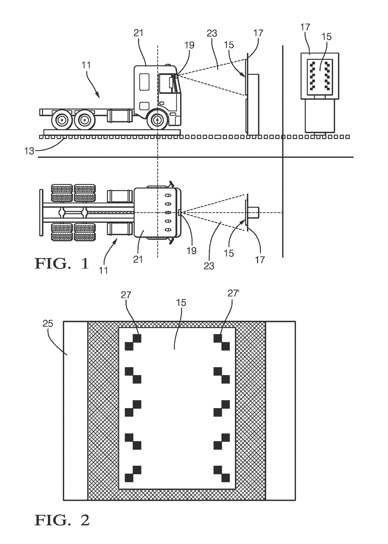
[0049]FIG. 1 shows a truck 11 at the end of a production line which the truck 11 has run through for its production. The truck 11 is moved by a conveyor system 13 and placed in front of a calibration pattern 15 situated on an upright panel 17. A camera 19 is mounted to a driver cabin 21 of the truck 11. The camera 19 is located at a precise position relative to the driver cabin 21. But since the driver cabin 21 is softly supported, for example by means of an air suspension, the height of the camera 19 can vary and is therefore unknown. However, the truck 11 is placed such that the camera 19 has a known distance to the calibration pattern 15.

[0050]The camera 19 has a field of view 23 depending on the orientation of the camera 19. Since the orientation of the camera 19 can vary, it has to be calibrated. To this purpose, the camera 19 acquires an image 25 of the calibration pattern 15. An exemplary such image 25 is shown in FIG. 2.

[0051]The calibration pattern 15 comprises ten sub-patt...


PUM


Abstract

Calibrating the orientation of a camera mounted to a vehicle includes providing calibration pattern defining at least two horizontal lines and two vertical lines; acquiring an image of the calibration pattern by means of the camera, the image having a first axis and a second axis corresponding to a horizontal axis and a vertical axis, respectively; identifying the horizontal lines and the vertical lines within the image; determining a horizontal vanishing point from the representations of the horizontal lines; determining a vertical vanishing point from the representations of the vertical lines; calculating a roll angle from the location of the horizontal vanishing point based on the image, calculating a yaw angle from a first coordinate of the horizontal vanishing point measured along the first axis, and calculating a pitch angle from a second coordinate of the vertical vanishing point measured along the second axis.

Description

TECHNICAL FIELD OF INVENTION[0001]The invention relates to a method for calibrating the orientation of a camera mounted to a vehicle.BACKGROUND OF INVENTION[0002]Recently, an increasing number of vehicles are provided with at least one camera mounted to the vehicle for capturing information about an environment of the vehicle. In particular, the camera is located at a front of the vehicle for acquisition of the road ahead. Image data thus obtained can then be used by various driver assistance systems, for example.[0003]From images acquired by such a camera spatial data about objects within the field of view of the camera can be extracted. However, this data are relative to the camera, but not (at least not directly) to the vehicle. Hence, for example positions of objects captured by the camera can only be determined with respect to the camera. To also obtain from images acquired by the camera the positions of such objects relative to the vehicle with high precision and reliability, ...

Claims


Application Information

Patent Timeline
IPC IPC(8): G06T7/80G06T7/73
CPCG06T7/80G06T7/73G06T2207/30252G06T2207/20076G06T7/74
Inventor DWORAKOWSKI, WALDEMARGONGOLEWSKI, KRZYSZTOFDLUGOSZ, RAFAL
Owner APTIV TECH LTD
Why Eureka
Try Eureka