
Relative attitude estimator for multi-payload attitude determination

a multi-payload, attitude determination technology, applied in vehicle position/course/altitude control, process and machine control, instruments, etc., can solve the problem that the actual payload attitude cannot be accurately derived in many cases, and achieve the effect of improving the determination of the attitude of the master payload and sufficient flexibility

Active Publication Date: 2006-10-17
THE BOEING CO
View PDF4 Cites 24 Cited by
  • Summary
  • Abstract
  • Description
  • Claims
  • Application Information

AI Technical Summary

Benefits of technology

[0011]The relative attitude estimator estimates the relative attitude between a “slave channel” attitude determination sensor and a “master channel” attitude determination sensor. The relative attitude estimator output allows “slave channel” measurements to be corrected to be consistent with the “master channel” and consequently used to improve the determination of the attitude of the master payload. The relative attitude estimator output also allows the absolute attitude of each of the slave payloads to be derived using the master payload absolute attitude and the relative attitudes of each of the other payloads.
[0012]The relative attitude estimator is also computationally economical. Most processor-intensive computations, such as matrix pseudo-inverse computations, are performed with a matrix that is known apriori, and hence, can be performed in advance, and do not require significant computer resources on board the spacecraft. The relative attitude estimator also includes sufficient flexibility to accommodate a wide variety of slave payloads, each with different relative attitude profiles (e.g. due to different thermal deformation), as well as a variety of pointing requirements for each slave payload.

Problems solved by technology

However, even if the nominal attitude of the payload relative to the spacecraft is known apriori, actual payload attitude cannot be accurately derived in many cases due to deviations from the nominal spacecraft-payload interface.

Method used


Image

  • Relative attitude estimator for multi-payload attitude determination
  • Relative attitude estimator for multi-payload attitude determination
  • Relative attitude estimator for multi-payload attitude determination

Examples


Embodiment Construction

[0024]In the following description, reference is made to the accompanying drawings which form a part hereof, and which is shown, by way of illustration, several embodiments of the present invention. It is understood that other embodiments may be utilized and structural changes may be made without departing from the scope of the present invention.

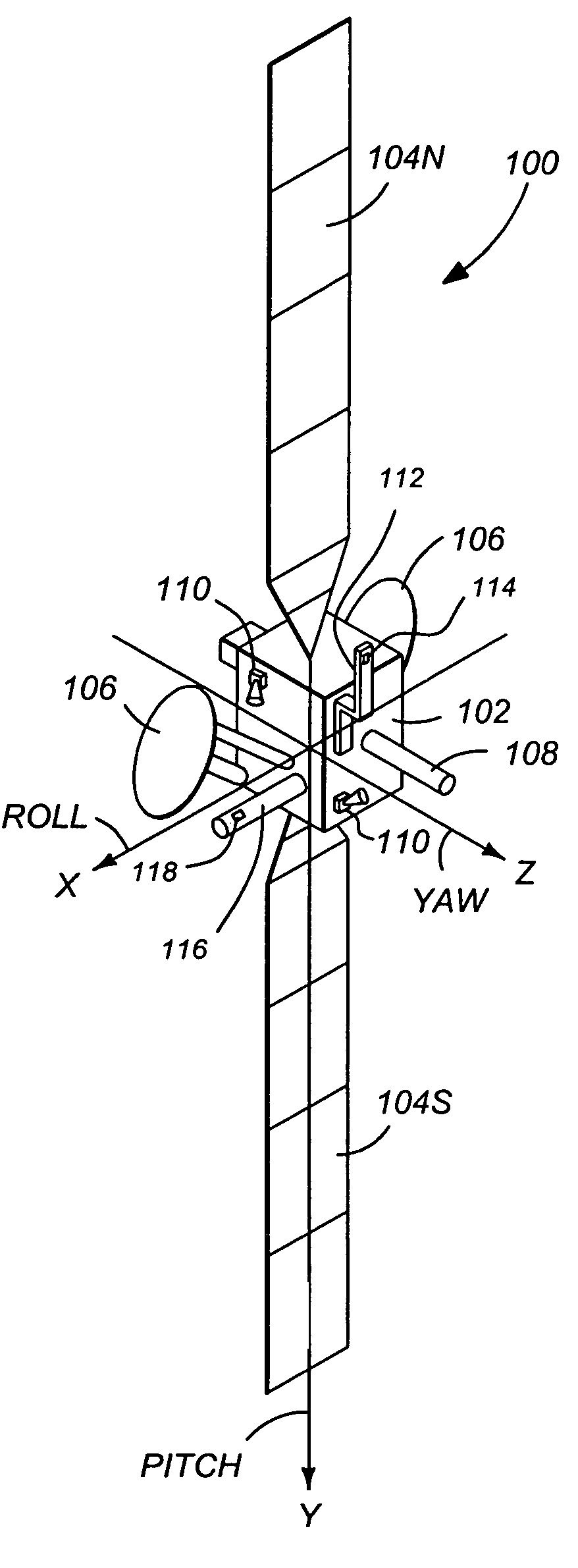
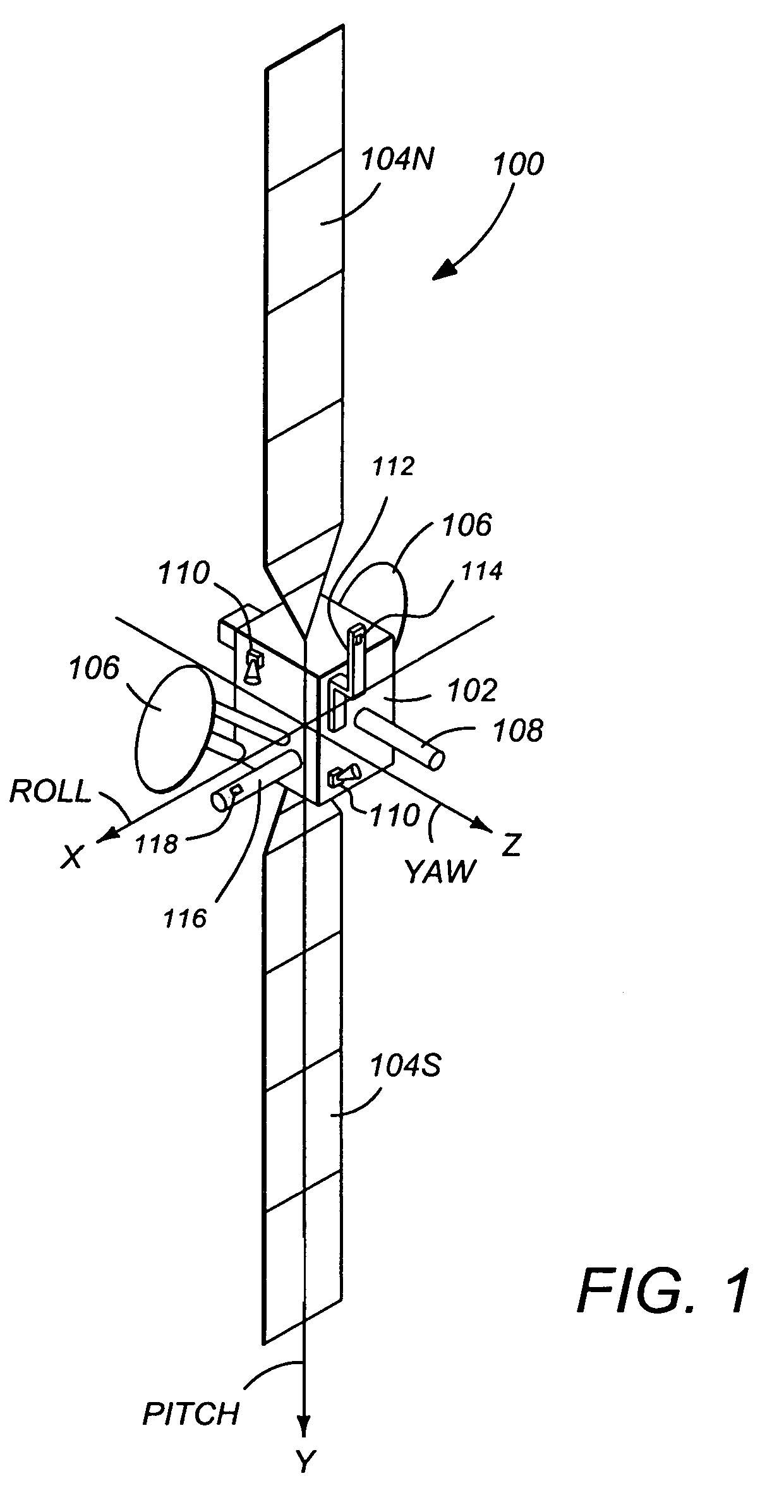
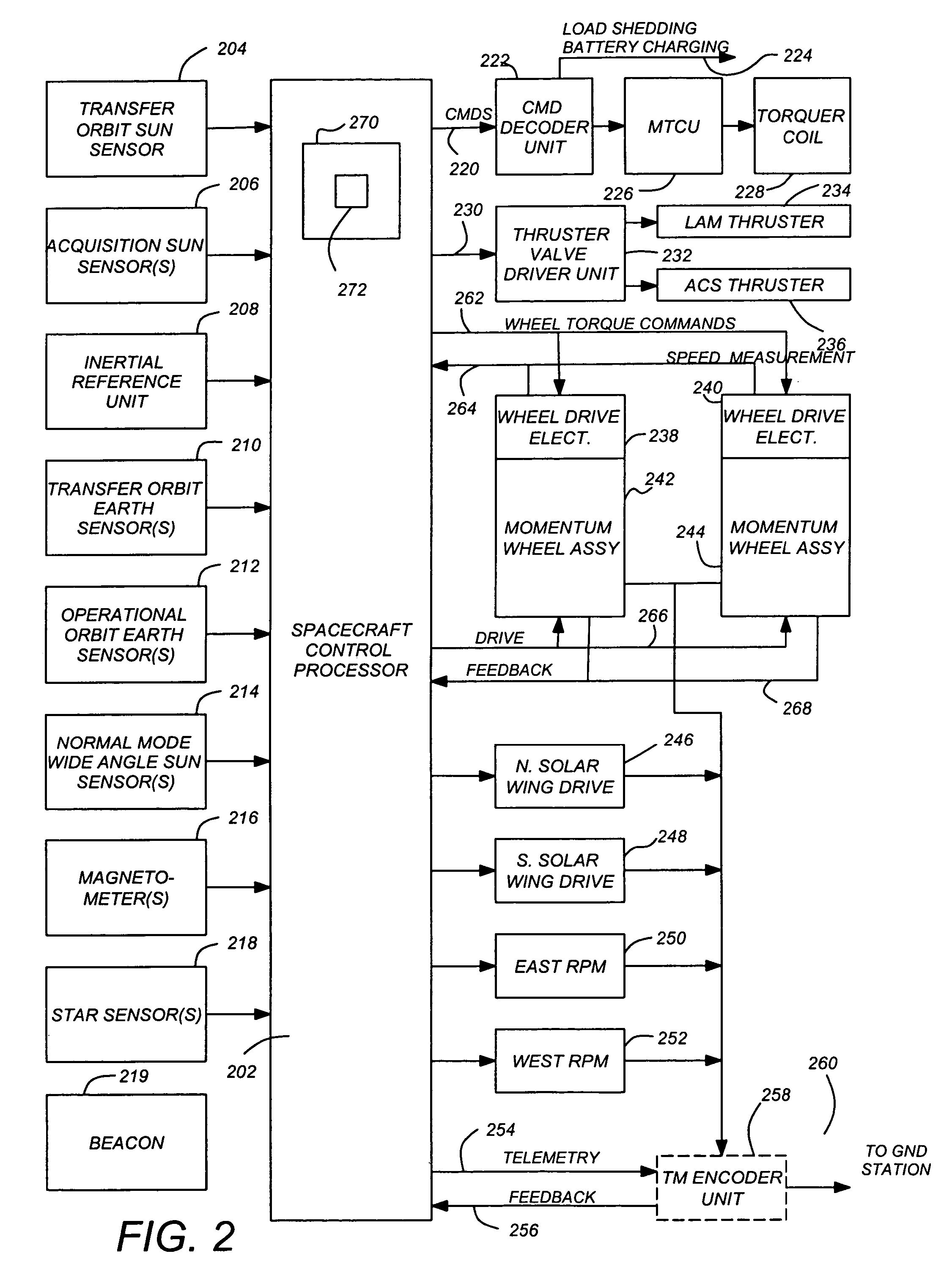
[0025]FIG. 1 illustrates a three-axis stabilized satellite or spacecraft 100. The spacecraft 100 is preferably situated in a stationary orbit about the Earth. The satellite 100 has a main body 102, a pair of solar panels 104, a pair of high gain narrow beam antennas 106, and a telemetry and command omni-directional antenna 108 which is aimed at a control ground station. The satellite 100 may also include one or more sensors 110 to measure the attitude of the satellite 100. These sensors may include sun sensors, earth sensors, and star sensors. Since the solar panels are often referred to by the designations “North” and “South”, the solar pan...


PUM


Abstract

A method and apparatus for estimating a slave payload attitude is disclosed. The method includes accepting a plurality of slave payload attitude measurements, deriving a model of the relative attitude of the slave payload and a master payload attitude at least in part from the plurality of slave attitude measurements, predicting the relative attitude between the slave payload attitude and the master payload attitude using the derived model, and estimating the relative attitude between the slave payload attitude and the master payload attitude at least in part from the predicted relative attitude between the slave payload attitude and the master payload attitude. Furthermore, the absolute attitude of the slave payload is computed using the relative attitude and the master payload attitude.

Description

CROSS-REFERENCE TO RELATED APPLICATIONS[0001]This application claims benefit of U.S. Provisional Patent Application No. 60 / 486,626, entitled “RELATIVE ATTITUDE ESTIMATOR FOR MULTI-PAYLOAD ATTITUDE DETERMINATION,” by Rongsheng Li, Hanching G. Wang and Yeong-Wei A. Wu, filed Jul. 11, 2003, which application is hereby incorporated by reference herein.[0002]This application is also related to U.S. Pat. No. 6,595,469, entitled “ATTITUDE CONTROL METHODS AND SYSTEMS FOR MULTIPLE-PAYLOAD SPACECRAFT,” by Rongsheng Li, Yeong-Wei A. Wu and Hanching Grant Wang, issued Jul. 22, 2003, which is hereby incorporated by reference herein.BACKGROUND OF THE INVENTION[0003]1. Field of the Invention[0004]The present invention relates to systems and methods for spacecraft navigation and control, and in particular to a system and method for determining the attitude of spacecraft payloads.[0005]2. Description of the Related Art[0006]Satellites and other spacecraft often include multiple payloads, one or more...

Claims


Application Information

Patent Timeline
Patent Type & Authority Patents(United States)
IPC IPC(8): G05D1/00G05D1/08B64G1/36B64G1/66
CPCB64G1/36B64G1/66
Inventor LI, RONGSHENGWANG, HANCHING GRANTWU, YEONG-WEI A.
Owner THE BOEING CO
Learn More