Collapsible container

a container and lid technology, applied in the field of collapsible containers, can solve the problems of inconvenient human use, inability to use automated equipment, and devices with hinge mechanisms that are difficult or inefficient to manufacture or clean, and achieve the effect of more rigidity and sturdy

Active Publication Date: 2009-06-23
REHRIG PACIFIC CO INC
View PDF14 Cites 31 Cited by
  • Summary
  • Abstract
  • Description
  • Claims
  • Application Information

AI Technical Summary

Benefits of technology

[0008]It is an object according to the present invention to provide a collapsible container that provides for the walls to be collapsed in an efficient manner and a relatively low package height for purposes of stacking and storing.
[0009]It is another object according to the present invention to provide a collapsible container having at least one pair of opposed overlapping side walls which are able to be folded in an efficient manner to provide a relatively low package height.
[0011]The present invention is also directed to a portable storage device having at least one interlocking member adjacent the latch. The interlocking member is inwardly offset from the outer surface of the wall so that when the walls are collapsed onto the base, the interlocking members will not interfere with the upstanding flange of the base nor will the base modification due to the interlocks be necessary, thus providing for a more rigid and sturdy base.
[0012]The collapsible container according to the present invention generally comprises a base wall and generally perpendicular first and second walls. A latch mechanism is integrally molded with the first wall and connects the first wall to the second wall. The latch mechanism includes a recess into which a portion of the second wall is received, thereby latching the first wall to the second wall. The latch mechanism further includes an outer release surface outward of the second wall and an inner release surface inward of the second wall, thus permitting the latch mechanism to be selectively disconnected from the second wall when the walls are assembled upon application of force to the outer release surface or the inner release surface, or to the outer wall surface due to the knock-down characteristics of this type of latch.

Problems solved by technology

Many such storage devices unlatch from outside the container, which is sometimes more efficient for a user, but not usable with automated equipment.
Other such storage devices unlatch from the inside, which is often desired for use with automated equipment, but less convenient for human users.
Moreover, such storage devices may have hinge mechanisms that are difficult or inefficient to manufacture or clean.
However, many collapsible containers have relatively tall walls which when assembled, provide a large container volume and depth.
Unfortunately, the overlapping walls typically result in less efficient stacking of the collapsed containers, because the overlapping second wall will be forced to sit high upon the first wall.
Containers that attempt to resolve the overlapping issue have been restricted, often requiring that the walls be folded in a particular sequence, or by having an unsymmetrical design or walls of varied heights.
While some of these solutions may be adequate, they may not provide the desired level of strength and rigidity.
While this provides some stability to stacked containers, this design may not be appropriate in every situation.
It may also not allow for stable stacking of collapsed containers.

Method used


Image

  • Collapsible container
  • Collapsible container
  • Collapsible container

Examples


Embodiment Construction

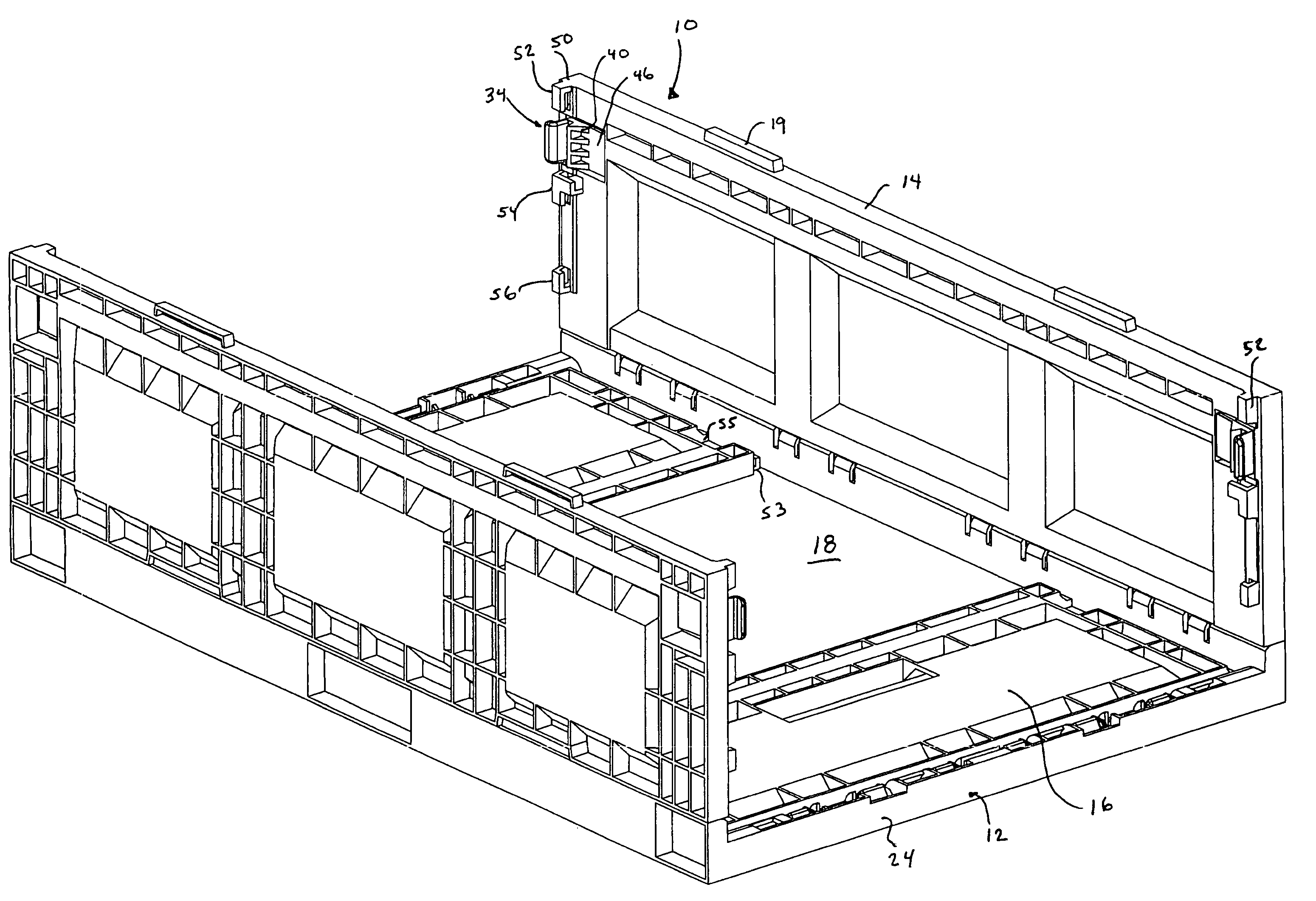
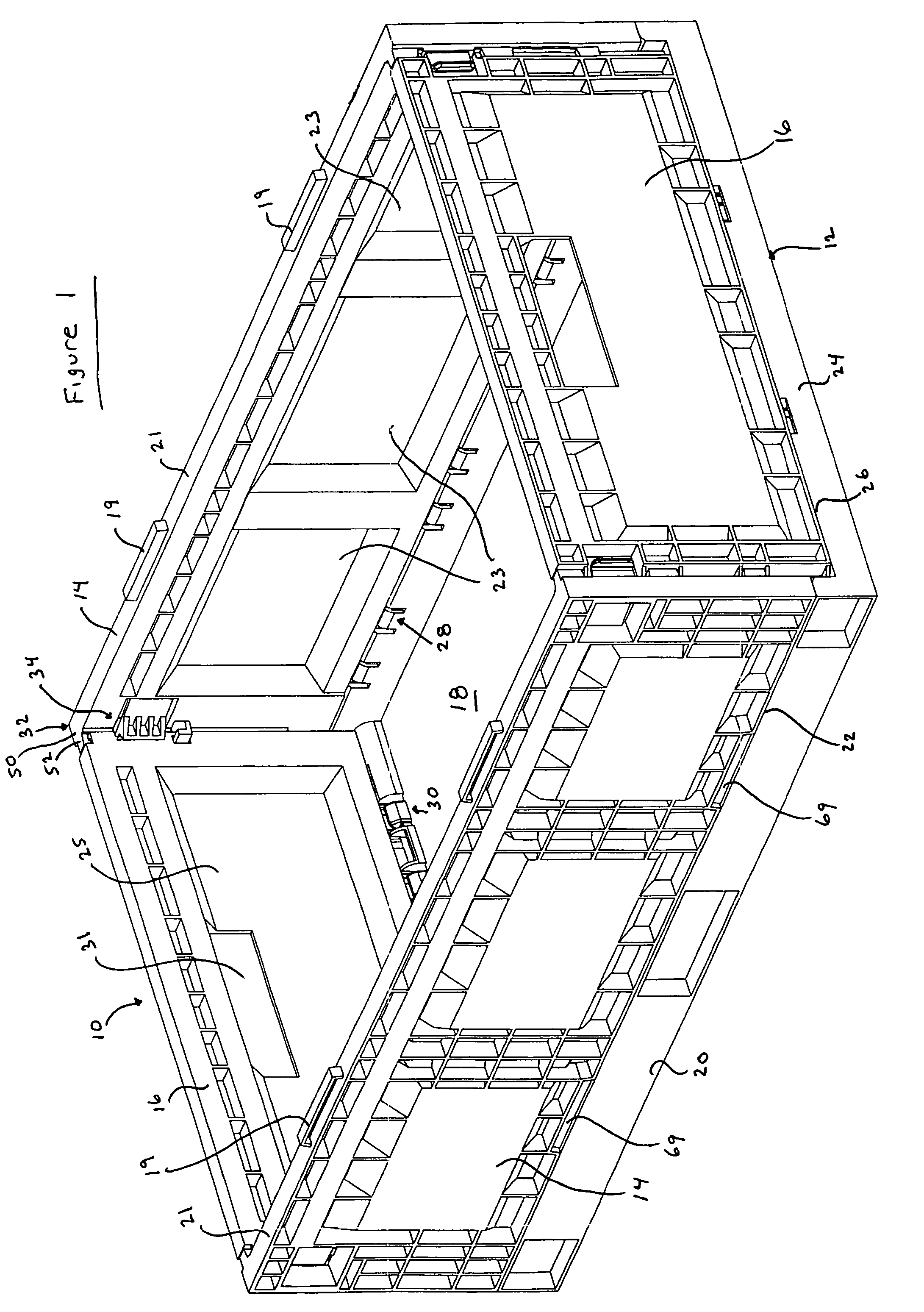
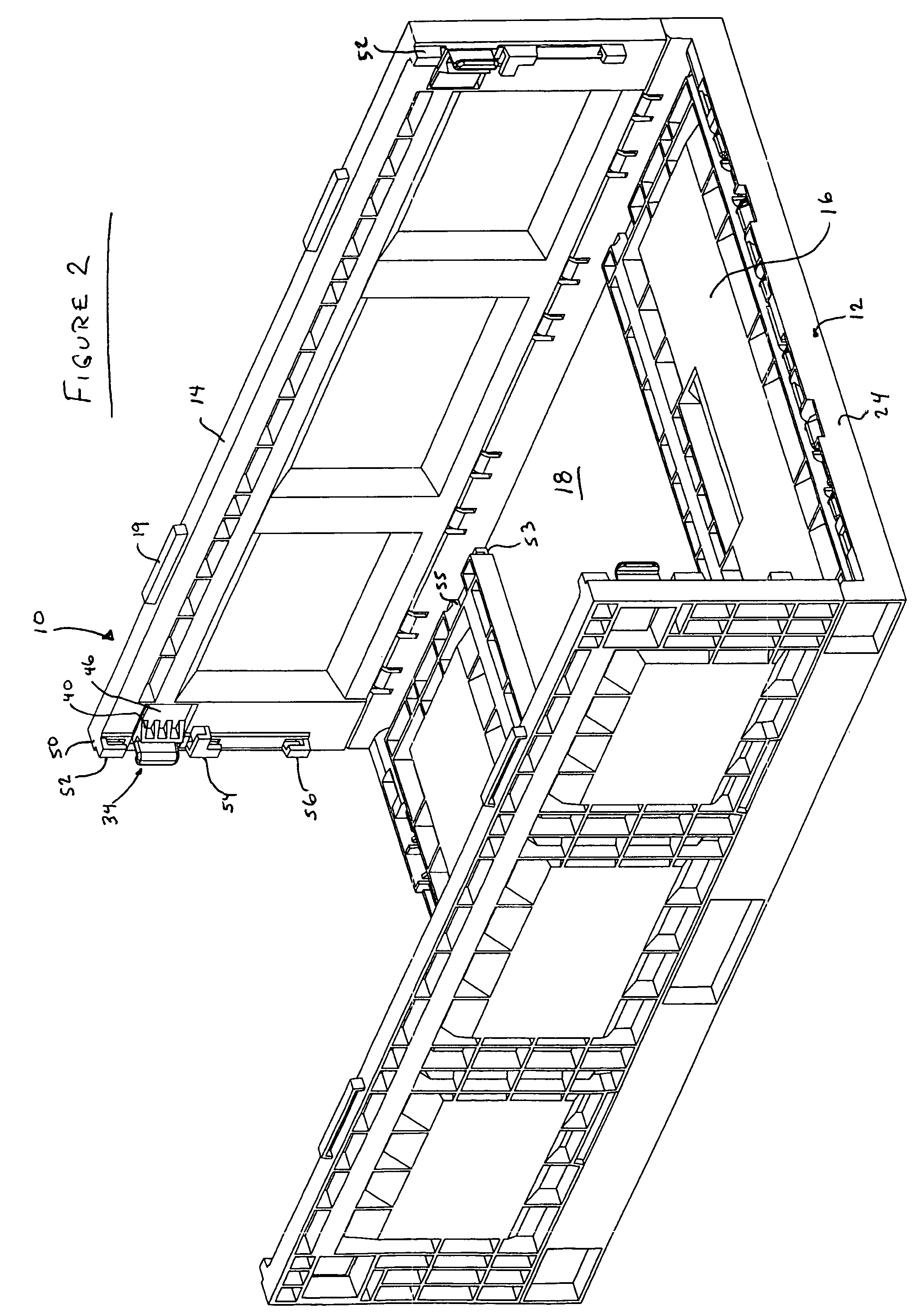
[0038]A collapsible container 10 according to the present invention is illustrated in FIG. 1. Container 10 is rectangular in shape and is generally symmetrical about each center line. Container 10 includes a base 12 and upstanding perpendicular opposing side walls 14 and opposing end walls 16. Base 12 includes a floor 18, a pair of first opposed base side portions 20 defining base side upper edges 22 along the sides of container 10, and a pair of second opposed base end portions 24 defining base end upper edges 26 along the ends of container 10. Side walls 14 are connected to base 12 by hinges 28, while the end walls 16 are connected to base 12 via hinges 30. As is shown, the side walls 14 and end walls 16 are collapsible by pivoting at hinges 28, 30 onto base 12. As shown in FIGS. 2 and 11, the crate can be collapsed inwardly for shipping or storage and can be quickly set up by pivoting walls 14, 16 about their respective hinges to the use position, generally perpendicular to floor...


PUM


Abstract

A collapsible container includes a plurality of collapsible walls, each pair of adjacent walls connected by a latch. Each latch can be selectively actuated from contact with the latch both from inside and the outside of the container, and further by inwardly directed forced to the outside of the wall first to collapse. Preferably, the latch includes a recess into which the adjacent wall is disposed when the latch is in the latched position. Preferably, the latch is unlatched by flexing the latch away from the adjacent wall by application of force on an inner release surface, inward of the recess or by actuation of an outer release surface, outward of the recess, or by the application of an inwardly directed forced to the walls that are first to collapse.

Description

BACKGROUND OF THE INVENTION[0001]The present invention relates generally to a collapsible container for storing and transporting goods.[0002]Portable storage devices that collapse are well known. Four walls each connected by a hinge to a base are selectively movable about the hinge between a use position, in which the wall is generally perpendicular to the base, and a collapsed position. Various mechanisms have been provided to connect adjacent walls at each corner to selectively lock the container in the use position. Many such storage devices unlatch from outside the container, which is sometimes more efficient for a user, but not usable with automated equipment. Other such storage devices unlatch from the inside, which is often desired for use with automated equipment, but less convenient for human users. Further, some containers do not require unlatching at all, but instead are of the knock-down variety which collapsible under suitable force to the wall to sufficient overcome th...

Claims


Application Information

Patent Timeline
Patent Type & Authority Patents(United States)
IPC IPC(8): B65D6/18B65D90/08
CPCB65D11/1833
Inventor SMYERS, JUSTIN M.APPS, WILLIAM P.
Owner REHRIG PACIFIC CO INC
Why Eureka
Try Eureka