Device for joining a longitudinal support with a bone fixation means

a technology of longitudinal support and bone fixation means, which is applied in the field of devices for connecting longitudinal supports with bone fixation means, can solve the problems of significant construction height of connecting elements and the space required for surgical instruments, and achieve the effects of reducing the number of surgical instruments and steps, reducing space, and reducing damag

Inactive Publication Date: 2005-09-29
DEPUY SYNTHES PROD INC
View PDF17 Cites 26 Cited by
  • Summary
  • Abstract
  • Description
  • Claims
  • Application Information

AI Technical Summary

Benefits of technology

[0005] The invention is intended to remedy this situation. The invention discloses a device that requires as little space as possible and which can be implanted with a reduced number of surgical instruments and steps. Specif

Problems solved by technology

The disadvantage of this prior art device is, on the one hand, the significant construction height of the connection element due in part to the ball and socket type connection between the spherical head of th

Method used


Image

  • Device for joining a longitudinal support with a bone fixation means
  • Device for joining a longitudinal support with a bone fixation means
  • Device for joining a longitudinal support with a bone fixation means

Examples


Embodiment Construction

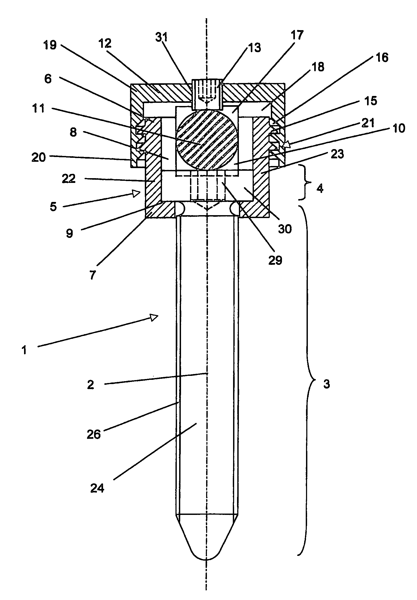
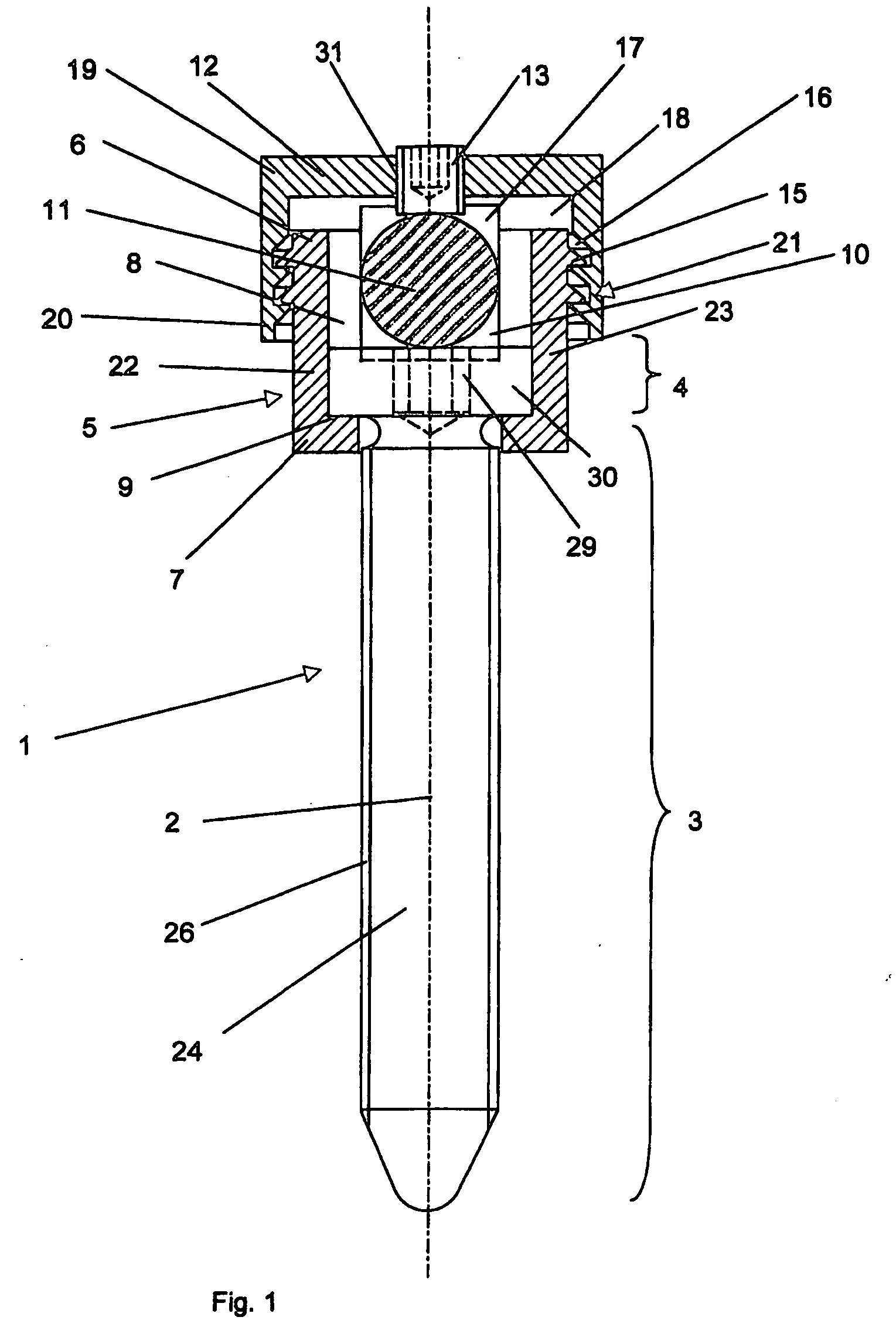
[0020]FIG. 1 illustrates a bone fixation means 1 designed as a pedicle screw together with a connection element 5, a longitudinal carrier 11, a sealing cap 12 axially displaceable over the upper end 6 of the connection element 5 and a tensioning means 13, i.e., a set screw, incorporated into the sealing cap 12. The bone fixation means 1 includes a front segment 3 and a rear segment 4, as shown, the front segment 3 has a screw shaft 24 with external thread 26 so that the bone fixation means 1 may threadedly engage a patient's pedicle, while the rear segment 4 has a circular-cylindrical screw head 30 having means 29, illustrated as a hexagon socket, for receiving a screwdriver, which are arranged at an end on the screw head 30. Alternatively, the means 29 for receiving a screwdriver may be in the form, for example, Torx or Phillips.

[0021] As shown, the connection element 5 generally is in the form of a hollow body having a central axis 2, an upper end 6, a lower end 7, and a cavity 8...


PUM


Abstract

The present invention is directed to a device for connecting a longitudinal carrier, for example, a longitudinal spinal rod, to a bone fixation means, for example, a pedicle screw. The device includes a connection element having an upper end, a lower end, and a cavity extending from the upper end to the lower end, the cavity having a reduced diameter portion at the lower end thereof thereby forming a shoulder for engaging the head of the bone fixation means. The connection element further including a transverse channel for receiving the longitudinal carrier. The device further includes a sealing cap incorporating tensioning means for securing the longitudinal carrier within the transverse channel. The sealing cap being secured to the connection element by way of arresting means, wherein the arresting means preferably includes a plurality of bulges, i.e., projections, formed on the outer surface of the connection element and the sealing cap includes a plurality of complementary depressions, i.e., recesses. The device may further incorporate securing means in order to prevent the bone fixation means from passing through the upper end of the cavity once the bone fixation means has been introduced into the connection element.

Description

BACKGROUND OF THE INVENTION [0001] The invention relates to a device for connecting a longitudinal carrier, for example, a longitudinal spinal rod, to a bone fixation means, for example, a pedicle screw. [0002] Devices are already known in the art for connecting pedicle screws to longitudinal carriers for fixing the vertebral column. For example, U.S. Pat. No. 5,584,834 to Errico discloses a device for connecting a bone fixation element to a longitudinal carrier. [0003] The connection device generally consists of a cylindrical central body, which is provided at its lower end with a slotted, tapered outer surface and a hollow-spherical cavity for receiving a spherical head of a bone fixation element and an externally threaded upper end. In its central section, the central body includes a channel, opened on the side, running perpendicular to the central axis for receiving the longitudinal carrier. The connection device further includes a locking collar and a rod securing sleeve. The l...

Claims


Application Information

Patent Timeline
IPC IPC(8): A61B17/70A61B17/58A61B17/86
CPCA61B2017/8655A61B17/7032A61B17/70
Inventor DONATH, RAOUL
Owner DEPUY SYNTHES PROD INC
Why Eureka
Try Eureka