Connector

Inactive Publication Date: 2009-06-23
CHENG UEI PRECISION IND CO LTD
View PDF25 Cites 2 Cited by
  • Summary
  • Abstract
  • Description
  • Claims
  • Application Information

AI Technical Summary

Benefits of technology

[0009]As described above, the insulating housing of the connector is capable of receiving the first terminal, the second terminal and the third terminal at the same time. The first terminal is adapted to connect with the first PCB and the charge plug for supplying electricity. The second terminal is adapted to connect with the first PCB and the second PCB, which makes the first PCB be connected with the second PCB electrically. The third terminal is adapted to connect with the first PCB and the antenna device for transmitting the electrical signal therebetween. That is, the connector collects all the performances of the antenna connector, the charge connector and the board-to-board connector. So, compared to the conventional connector used in the bluetooth earphone, the bluetooth earphone using the connector not only reduces the weight and volume, but also reduces the complexity of the manufacture and assembly.

Problems solved by technology

So, compared to the conventional connector used in the bluetooth earphone, the bluetooth earphone using the connector not only reduces the weight and volume, but also reduces the complexity of the manufacture and assembly.

Method used


Image

  • Connector
  • Connector
  • Connector

Examples


Embodiment Construction

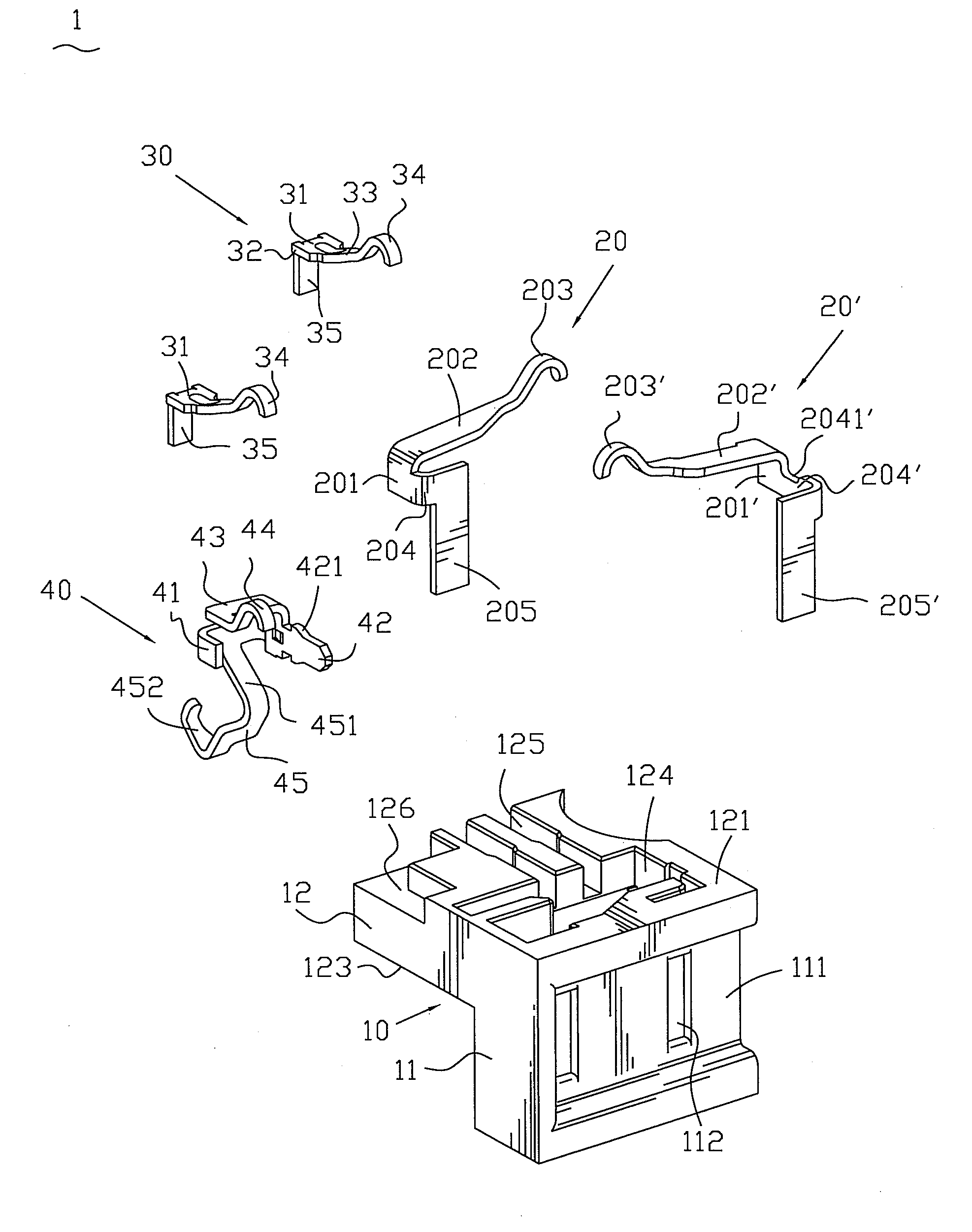
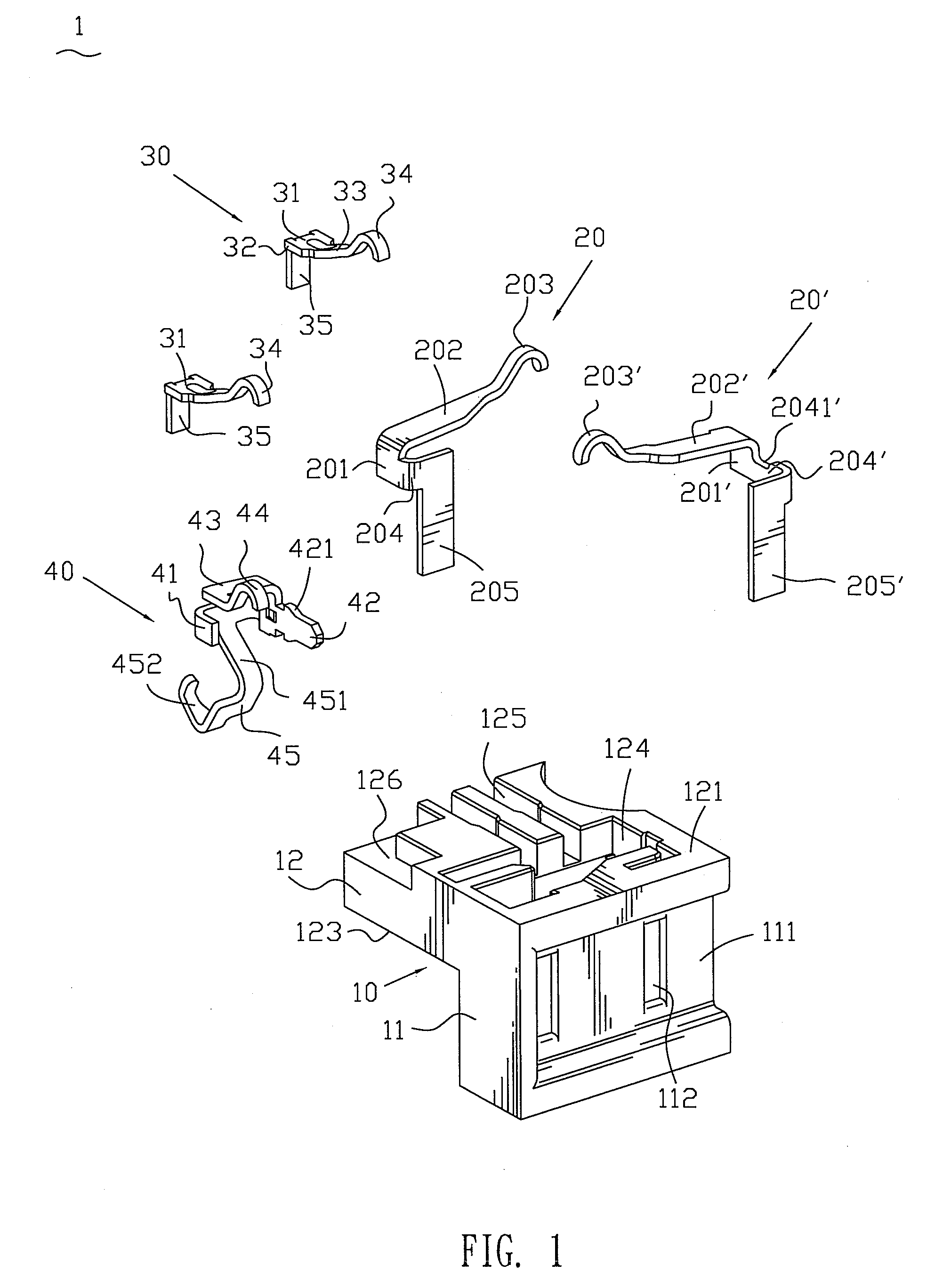
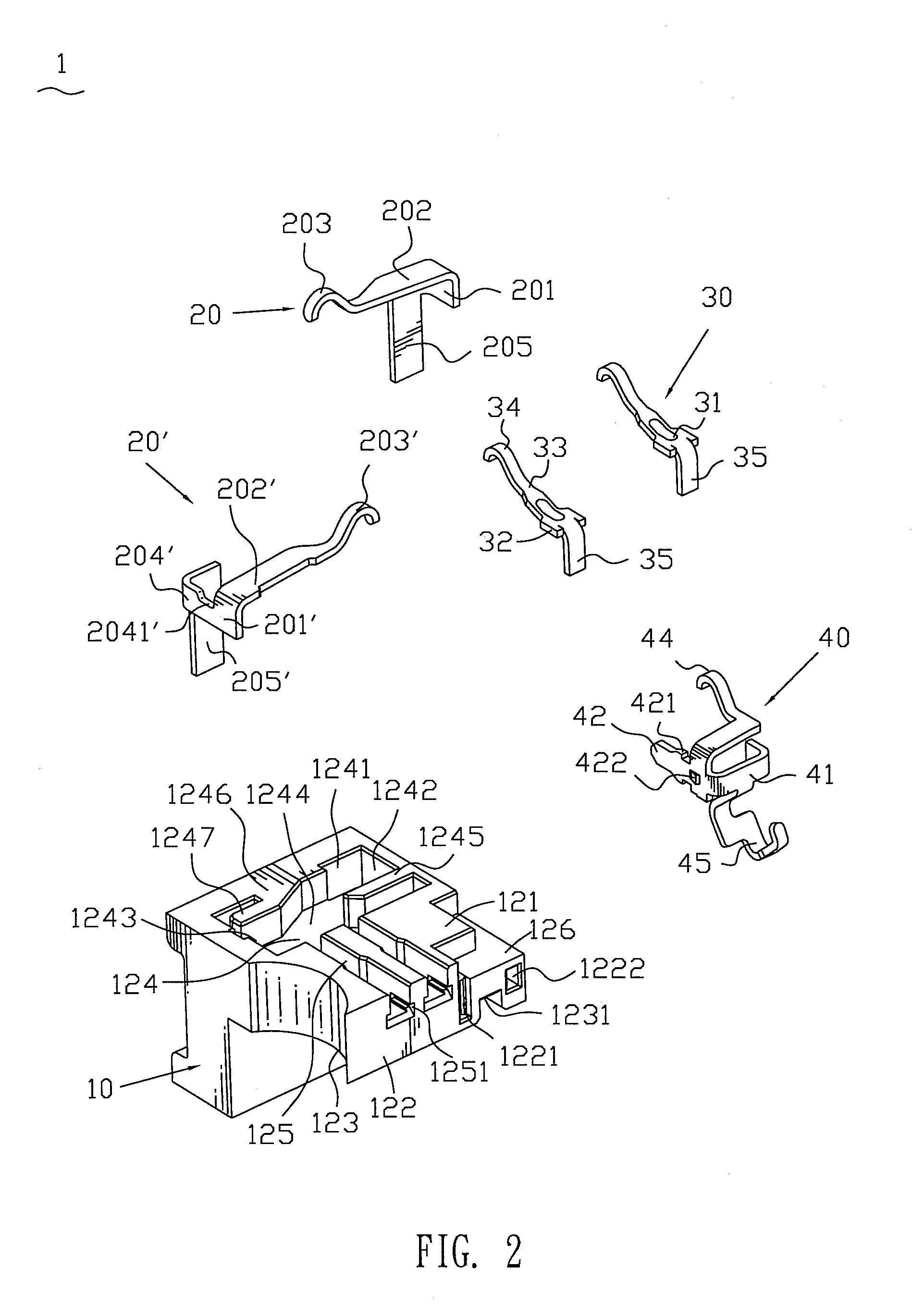
[0017]With reference to FIG. 1, FIG. 2 and FIG. 3, a connector 1 includes an insulating housing 10, two first terminals 20, 20′, a second terminal 30 and a third terminal 40 all of which are assembled in the insulating housing 10.

[0018]The insulating housing 10 has a mating body 11 and a receiving body 12 extending outwards perpendicularly from an upper portion of the mating body 11. The mating body 11 defines a mating surface 111 thereon. The mating surface 111 in turn defines two cavities 112 therein for receiving terminals of a charge plug (not shown). The receiving body 12 defines a top surface 121, a side surface 122 and a bottom surface 123. The top surface 121 defines a first terminal recess 124. The first terminal recess 124 is approximately of rectangle shape. The first terminal recess 124 defines a first sidewall 1241 near the mating surface 111, a second sidewall 1242 and a third sidewall 1243 respectively contiguous to the first sidewall 1241, and a bottom 1244. A first ...


PUM


Abstract

A connector has an insulating housing. The insulating housing has a mating body and a receiving body connected with the mating body. The mating body has a mating surface which defines at least one cavity. The receiving body defines a top surface, a bottom surface and a side surface. A first terminal has a first contacting portion positioned on the top surface and adapted for being connected with a first printed circuit board, and a first connecting portion protruding into the corresponding cavity. A second terminal has a second contacting portion also positioned on the top surface and a second connecting portion extending out of the side surface and adapted for being connected to a second printed circuit board. A third terminal has a third contacting portion also positioned on the top surface and an antenna-connecting portion extending out of the bottom surface for connecting an antenna device.

Description

BACKGROUND OF THE INVENTION[0001]1. Field of the Invention[0002]The present invention relates to a connector, and more particularly to a connector mainly applied in bluetooth earphone.[0003]2. The Related Art[0004]A bluetooth earphone is a wireless earphone manufactured via adapting the bluetooth technology for short-distance signal transmission. The bluetooth earphone offers the advantages of excellent compatibility, high quality and attractive appearance. As a result, the bluetooth earphone has been widely used in various electronic devices, such as mobile phone, PDA and so on, and attracts many people who want to release their hands or are in pursuit of the fashion. However, with recent improvement in economic status and resulting interest in well-being, the requirement for compact size and high portability of the bluetooth earphone increases gradually.[0005]Generally, the conventional bluetooth earphone has a first printed circuit board (herein referred as to PCB), a second PCB,...

Claims


Application Information

Patent Timeline
IPC IPC(8): H01R12/00
CPCH01R24/50H01R13/41H01R13/50H01R2103/00H01R2201/02Y10S439/916
Inventor CHIANG, SHU-MANYANG, MEI-CHUAN
Owner CHENG UEI PRECISION IND CO LTD
Why Eureka
Try Eureka