
Pixel interpolation method

a pixel interpolation and interpolation technology, applied in the field of pixel interpolation, can solve the problems of content-dependent misinterpolation, and achieve the effect of improving the interpolation accuracy of pixel interpolation technology

Active Publication Date: 2009-06-23
MEGACHIPS
View PDF14 Cites 16 Cited by
  • Summary
  • Abstract
  • Description
  • Claims
  • Application Information

AI Technical Summary

Benefits of technology

The present invention provides a technique for improving the interpolation accuracy in a pixel interpolation technology using a plurality of correlations. By obtaining correlations in multiple directions and using them as the basis for judgment, interpolation can be performed with higher accuracy. This technique is effective even in the future case in which increasing number of imaging devices may have pixels arrayed in diagonal directions.

Problems solved by technology

However, the interpolation is an operation of estimating pixel data of a target pixel from pixel data of neighboring pixels around the target pixel, and accordingly, misinterpolation may be performed depending on the contents of an image.
The above method is to improve the accuracy in pixel interpolation by evaluating the correlations in diagonal directions, but is a mere extension of the interpolation method using correlations in the vertical and horizontal directions, which therefore may cause misinterpolation in some cases.

Method used


Image

  • Pixel interpolation method
  • Pixel interpolation method
  • Pixel interpolation method

Examples


first preferred embodiment

Processing on Pixel Array of General RGB Bayer Pattern

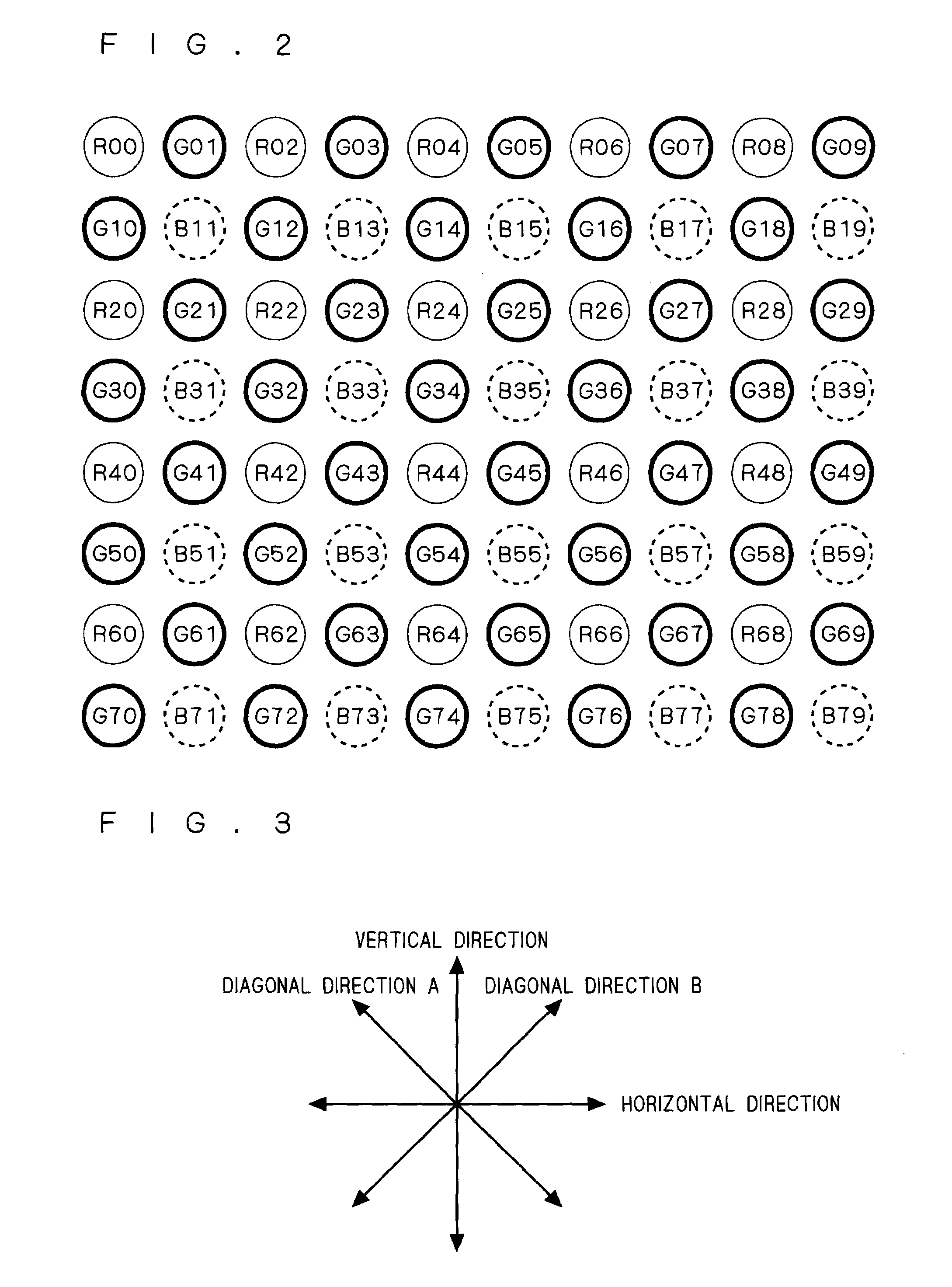
[0030]A pixel interpolation method according to a first preferred embodiment of the present invention will be described. In the present embodiment, a pixel signal output from the CCD 2 is a pixel signal of general RGB Bayer pattern as shown in FIG. 2.

[0031]As to two-digit numbers following the characters R (red), G (green) and B (blue) respectively representing color components shown in FIG. 2, the first digit denotes the row number of pixel array, and the second digit denotes the column number of pixel array. In this example, each even-numbered line is a line in which an R pixel and a B pixel are read out alternately like RGRG, and each odd-numbered line is a line in which a G pixel and a B pixel are read out alternately like GBGB.

[0032]FIG. 3 is a diagram illustrating four directions in which correlations are to be evaluated in the pixel array shown in FIG. 2. In the present embodiment, two pairs of two directions perpendicular...

second preferred embodiment

Processing on Pixel Array of RGB Bayer Pattern Turned 45 Degrees

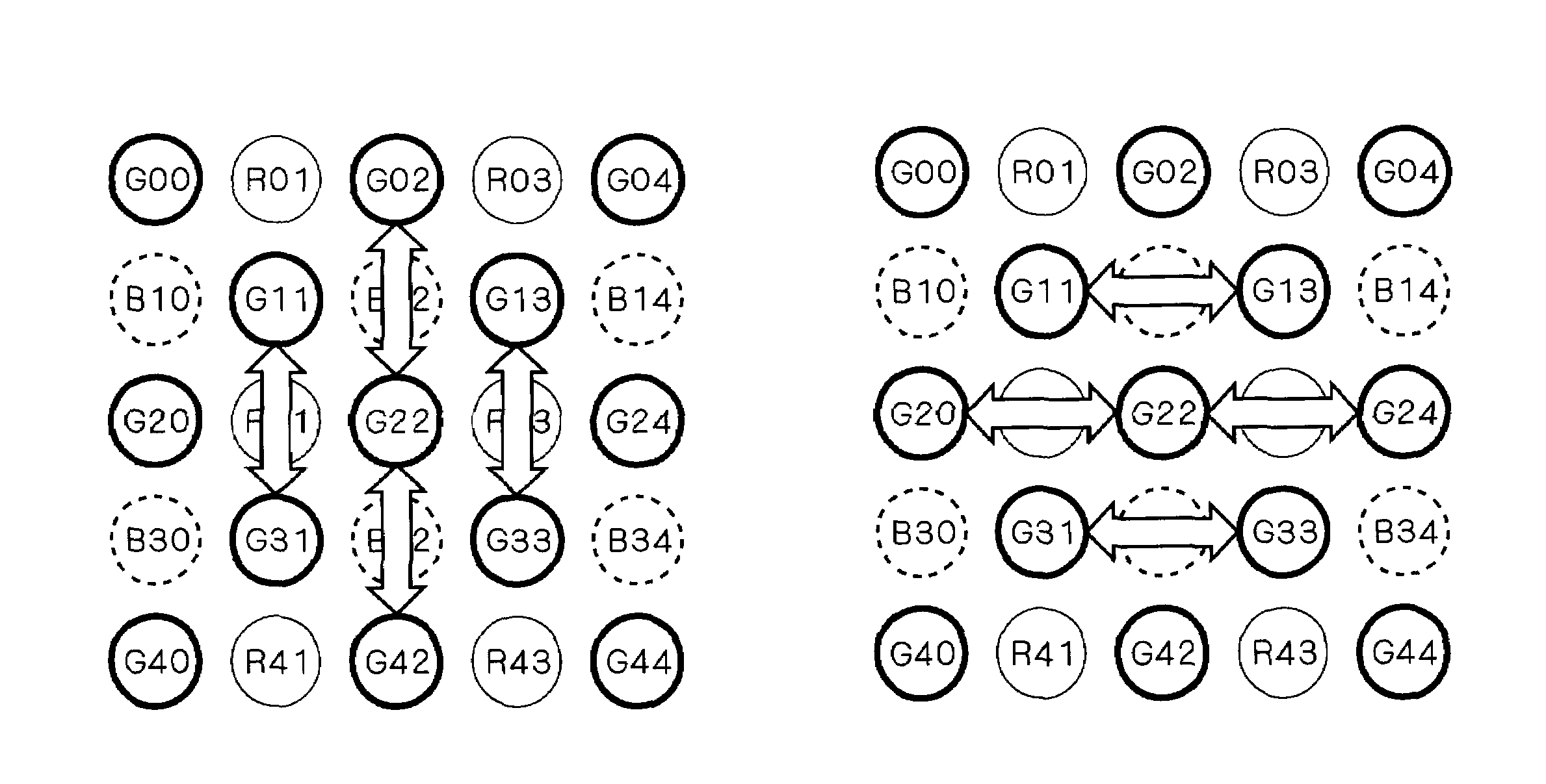
[0088]A pixel interpolation method according to a second preferred embodiment of the present invention will be described. The CCD 2 according to the present embodiment has a pixel array as shown in FIG. 6. More specifically, the general RGB Bayer pattern shown in FIG. 2 is turned 45 degrees. For instance, CCDs having such pixel array are known as honeycomb CCDs.

[0089]A pixel signal output from the CCD 2 is a pixel signal having an array as shown in FIG. 7. In this example, an R (red) pixel and a B (blue) pixel are read out alternately like RBRB in each even-numbered line, and G (green) pixels are continuously read out like GGGG in each odd-numbered line. In this manner, the output signal arrangement differs from that of the first preferred embodiment, and therefore, a method is employed which is different from that described in the first preferred embodiment.

[0090]In the present embodiment, two pairs of correlated direc...


PUM


Abstract

Correlation values in the vertical direction, horizontal direction and two diagonal directions are obtained in a pixel signal of RGB Bayer pattern. The correlation values are calculated using G signals. Between a first pair of the vertical and horizontal directions and a second pair of the two diagonal directions, one pair having a greater correlation difference is selected. Then, a direction having a stronger correlation is selected in the selected pair having a greater correlation difference, and pixel interpolation is performed in the selected direction. Alternatively, pixel interpolation is performed following assignment of weights in two directions of the selected pair having a greater correlation difference in accordance with the proportion of their correlations.

Description

BACKGROUND OF THE INVENTION[0001]1. Field of the Invention[0002]The present invention relates to a pixel interpolation method to be adapted in digital cameras or the like.[0003]2. Description of the Background Art[0004]A CCD imaging device for use in digital cameras or the like photoelectrically transfers light received through a color filter to output pixel data. Such color filter includes an RGB color filter, a YMCK color filter and the like. Through a single-chip color filter, single-color pixel data is output per pixel. For instance, when employing the RGB color filter, pixel data having one of R (red), G (green) and B (blue) color components is output per pixel.[0005]Therefore, in the case of pixel data output from a CCD imaging device equipped with a single-chip color filter, single-color image data is output per pixel, and thus image data of other color components is to be interpolated. Various algorithms are used in the interpolation.[0006]However, the interpolation is an op...

Claims


Application Information

Patent Timeline
Patent Type & Authority Patents(United States)
IPC IPC(8): H04N3/14G06K9/00H04N5/335H04N9/04H04N9/083H04N23/40H04N9/03H04N23/12
CPCG06T3/4015H04N9/045H04N9/07H04N23/843H04N23/12H04N25/134
Inventor HASEGAWA, HIROMU
Owner MEGACHIPS
Learn More