Position detector

a detector and position technology, applied in the direction of speed measurement using gyroscopic effects, electrical/magnetically converting sensor output, instruments, etc., can solve the problem of inability to extract offset components, and achieve the effect of eliminating accuracy-degrading components, accurately identifying offsets, and accurate identifying offsets

Inactive Publication Date: 2015-09-22
OKUMA CORP
View PDF16 Cites 9 Cited by
  • Summary
  • Abstract
  • Description
  • Claims
  • Application Information

AI Technical Summary

Benefits of technology

[0013]By employing the present invention, components corresponding to offset components can be extracted through correlation calculations of an output from the radius calculator and two signals from the position sensor, even without using Fourier transform. Therefore, it is possible to accurately identify offsets as in the technique described in JP 2008-232649 A. Also, even at a rotational speed at which the position changes by λ / 2n or greater per sample period of the A / D converter, it is possible to accurately identify offsets. Therefore, even during high-speed rotation, it is possible to precisely identify changes in offsets over time, to eliminate accuracy-degrading components, and to significantly improve the interpolation accuracy. As a result, both high accuracy and high speed can be simultaneously achieved in a position detector.

Problems solved by technology

As a result, there is a problem in that, at a speed at which the position changes by λ / 2n or greater per AD sample period, because it is impossible to perform a Fourier analysis, it is impossible to extract offset components.

Method used


Image

  • Position detector
  • Position detector
  • Position detector

Examples


first embodiment

(First Embodiment)

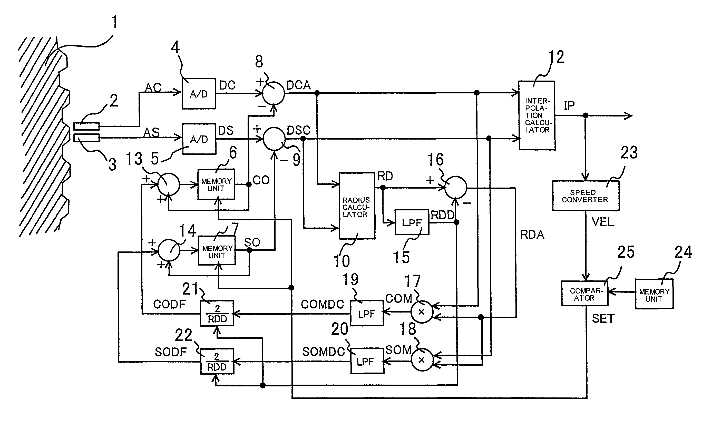
[0018]A first embodiment of the present invention will be described below with reference to the drawings. FIG. 1 is a block diagram showing a structure of a position detector according to the first embodiment of the present invention. In FIG. 1, elements having the same functions as those shown in FIG. 4 are denoted by the same reference numerals, and their description is not repeated.

[0019]As shown in FIG. 1, analog signals AC and AS output from two types of detection coils 2 and 3 are converted by A / D converters 4 and 5 into digital signals DC and DS. Signals DCA and DSC obtained by subtracting offset components CO and SO measured at the time of manufacture from the digital signals DC and DS using subtractors 8 and 9 are input to a radius calculator 10. The radius calculator performs a calculation according to the equation (1) to output a radius value RD.

[0020]The radius value RD output from the radius calculator 10 is input to a low-pass filter (LPF) 15, and a s...

second embodiment

(Second Embodiment)

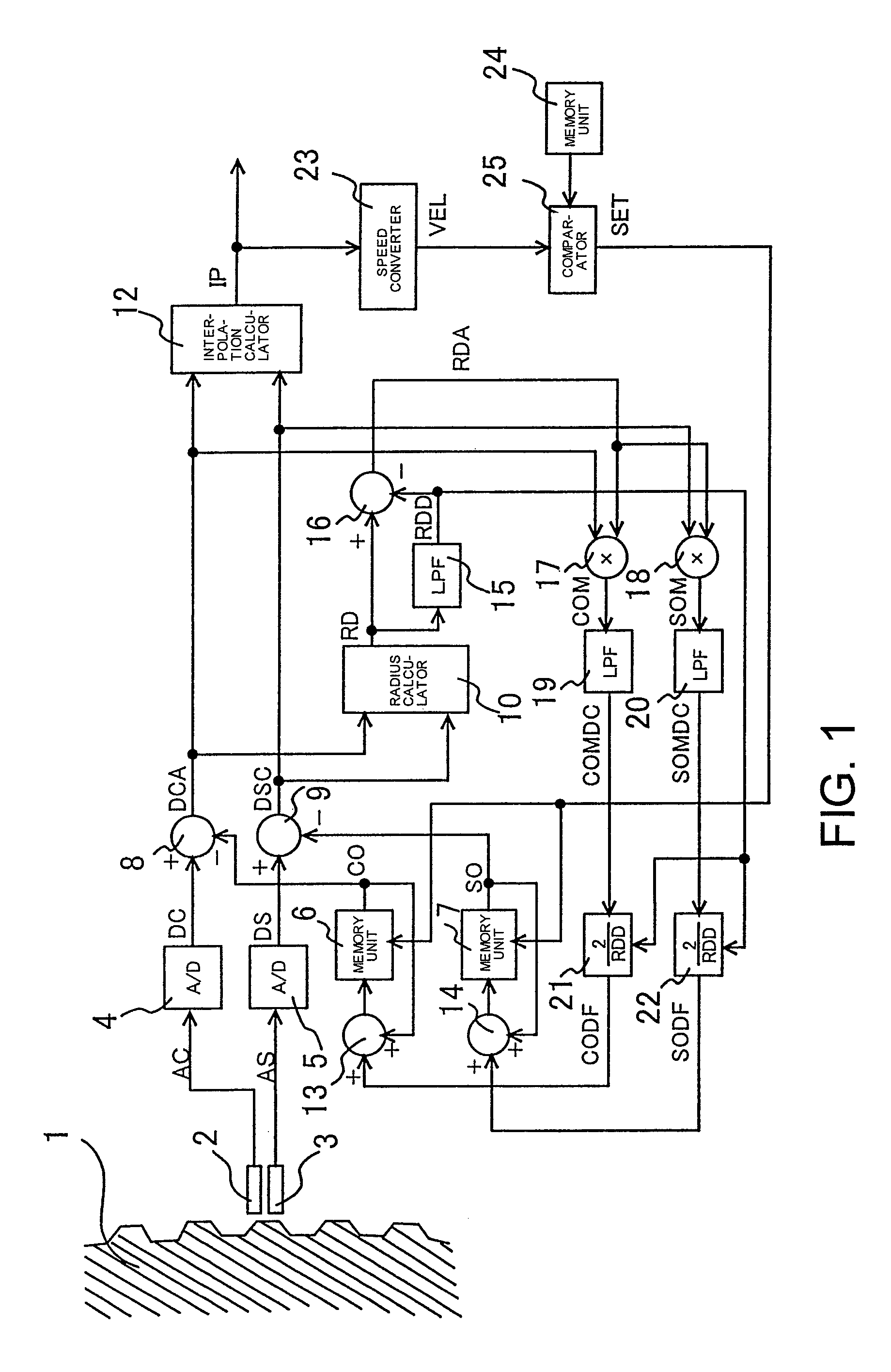
[0024]Next, a second embodiment will be described. FIG. 2 is a diagram showing a structure of a position detector according to the second embodiment. Although, in the first embodiment, the signals DCA and DSC in which offset components have been eliminated are used as inputs to the radius calculator 10, the signals DC and DS in which offset components have not been eliminated are used as inputs to the radius calculator 10 in the present embodiment, as shown in FIG. 2. In this case, because values output from the calculators 21 and 22 are offset components CO and SO of the signals DC and DS, adders 13 and 14 as shown in FIG. 1 are unnecessary. However, in this structure, there is a possibility that, when offset components included in the position sensor output signals are large, the offset identification accuracy may decrease.

third embodiment

(Third Embodiment)

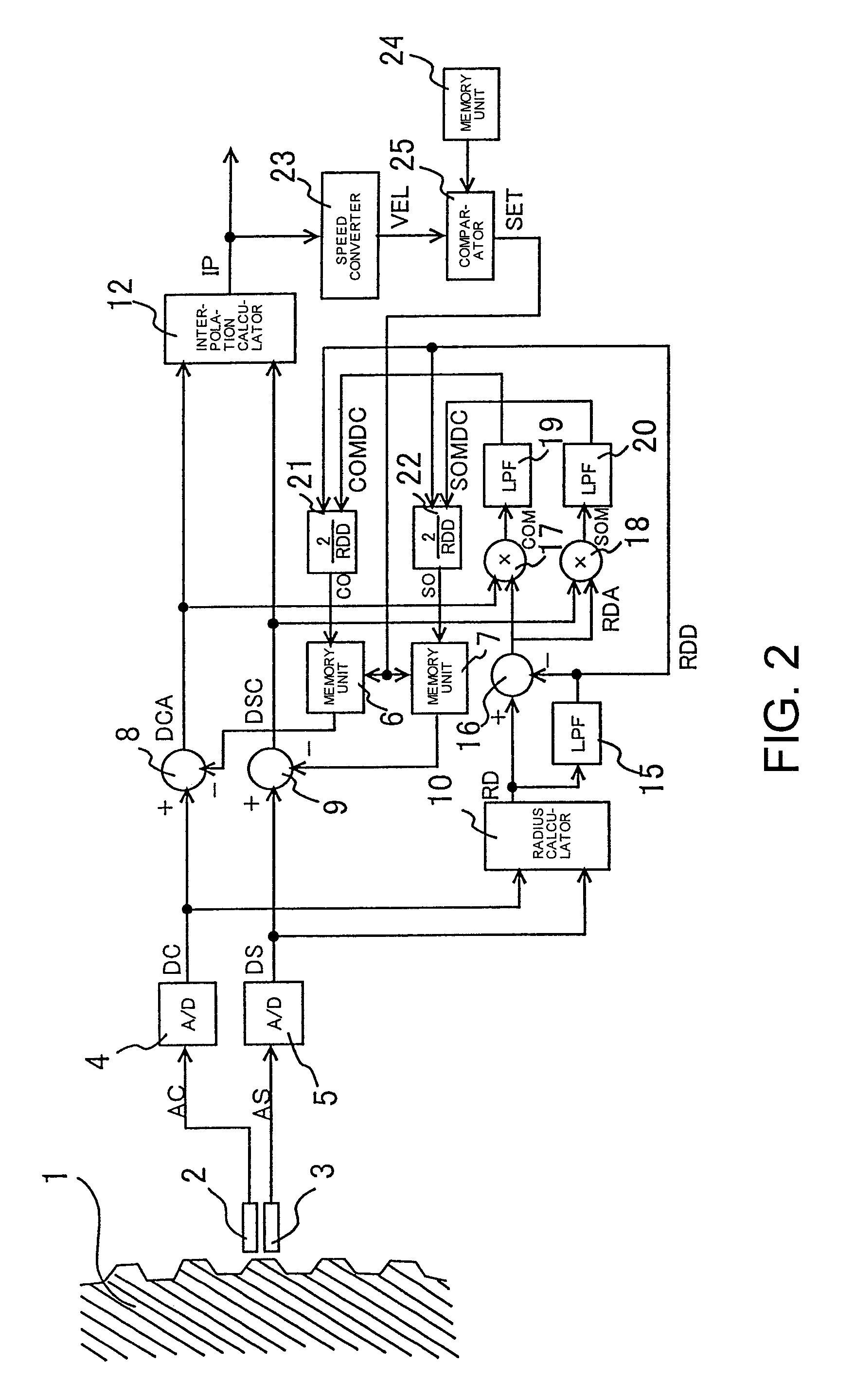
[0025]Next, a third embodiment will be described. FIG. 3 is a diagram showing a structure of a position detector according to the third embodiment. Although, in the first embodiment, the low-pass filters 19 and 20 are used as means for extracting DC components of the signals COM and SOM output from the multipliers 17 and 18, average values for a period of time during which the position sensor output signals change by one cycle are extracted as DC components in the third embodiment, as shown in FIG. 3.

[0026]More specifically, averaging processors 26 and 27 output signals ACOMDC and ASOMDC obtained by averaging m values for the signals COM and SOM output from the multipliers 17 and 18 each time an interpolation value IP output from the interpolation calculator 12 changes by λ / m (λ represents an amount of movement for one pitch of the rotor 1, and m represents an integer greater than or equal to 2). The signals ACOMDC and ASOMDC are DC components of the signals COM an...


PUM


Abstract

A position detector includes detection coils for outputting two sinusoidal signals that have phases shifted from each other by 90 degrees; subtractors for eliminating offset components included in output signals DCA and DSC output from the detection coils; an interpolation calculator for converting the two signals DCA and DSC in which the offset components have been eliminated into position information IP; a radius calculator for calculating a root-sum-square of the two signals DC and DS output from the detection coils; correlation calculators for respectively multiplying a fluctuation component RDA of an output from the radius calculator by the signals DCA and DSC in which the offset components have been eliminated; low-pass filters (LPFs) for extracting DC components of output values output from the correlation calculators; and an outputter for outputting offset components including offset displacement fractions based on output values COMDC and SOMDC output from the LPFs.

Description

CROSS-REFERENCE TO RELATED APPLICATIONS[0001]This application claims priority to Japanese Patent Application No. 2010-170840, filed on Jul. 29, 2010, which is incorporated herein by reference in its entirety.TECHNICAL FIELD[0002]The present invention relates to a position detector that converts, into position information, output signals output from a position sensor which outputs two signals that vary sinusoidally with respect to a measured displacement and have phases shifted from each other by 90 degrees.RELATED ART[0003]Position detectors for detecting a position based on output signals output from a position sensor which outputs two signals that vary sinusoidally in accordance with a displacement of a measurement target and have phases shifted by 90 degrees have been heretofore known. In such devices, offset components included in the output signals output from the position sensor are obtained using a radius calculator that calculates a root-sum-square of the two signals to auto...

Claims


Application Information

Patent Timeline
Patent Type & Authority Patents(United States)
IPC IPC(8): G01C9/00G01D5/245G01D5/244
CPCG01D5/2451G01D5/2448
Inventor SHIMADA, TAISHIHAYASHI, YASUKAZU
Owner OKUMA CORP
Why Eureka
Try Eureka