Position detector
a detector and position technology, applied in the field of position detectors, can solve the problems of inability to extract offset components, and achieve the effects of eliminating accuracy-degrading components, accurately identifying offsets, and accurate identification of offsets
- Summary
- Abstract
- Description
- Claims
- Application Information
AI Technical Summary
Benefits of technology
Problems solved by technology
Method used
Image
Examples
first embodiment
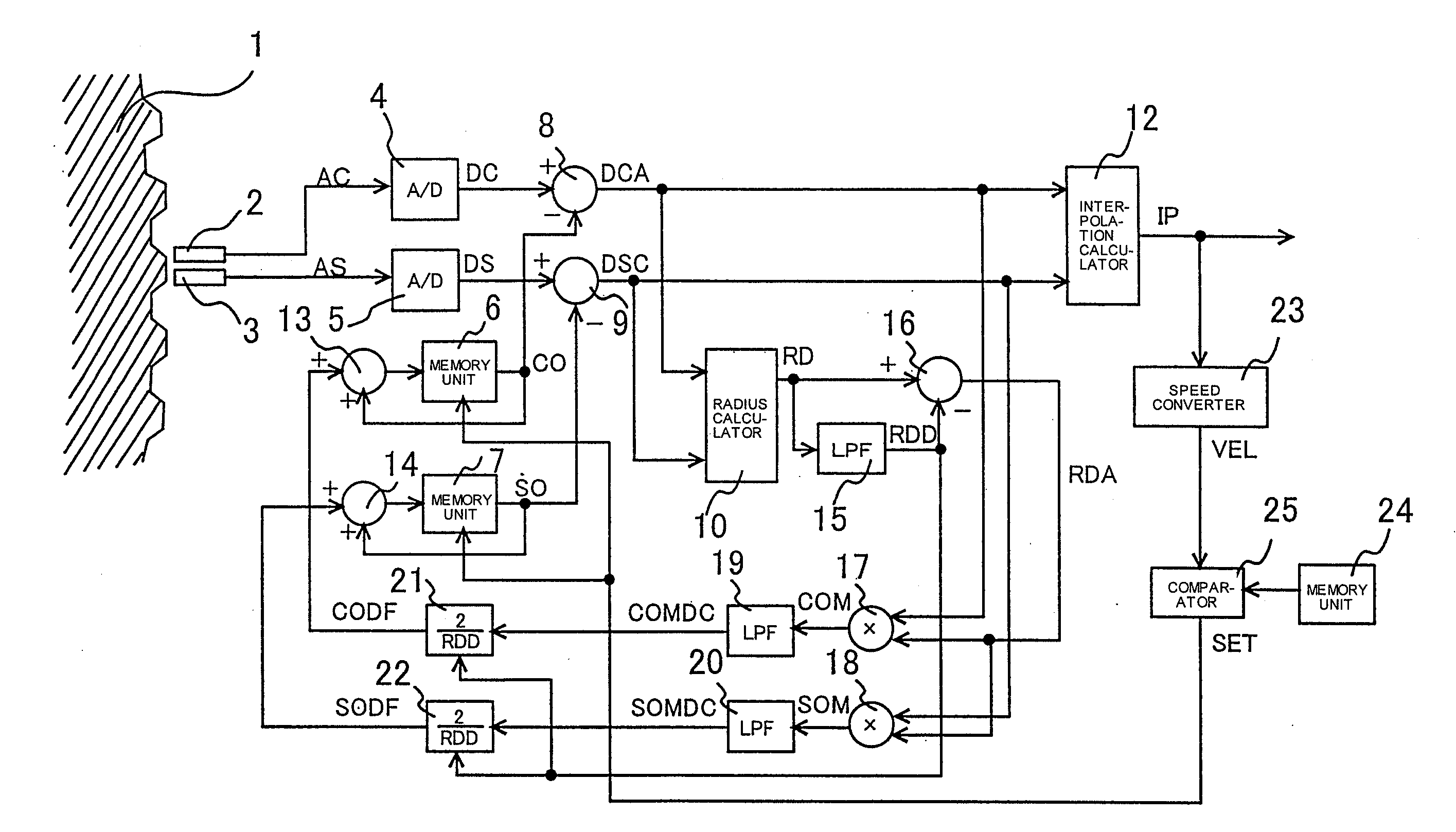
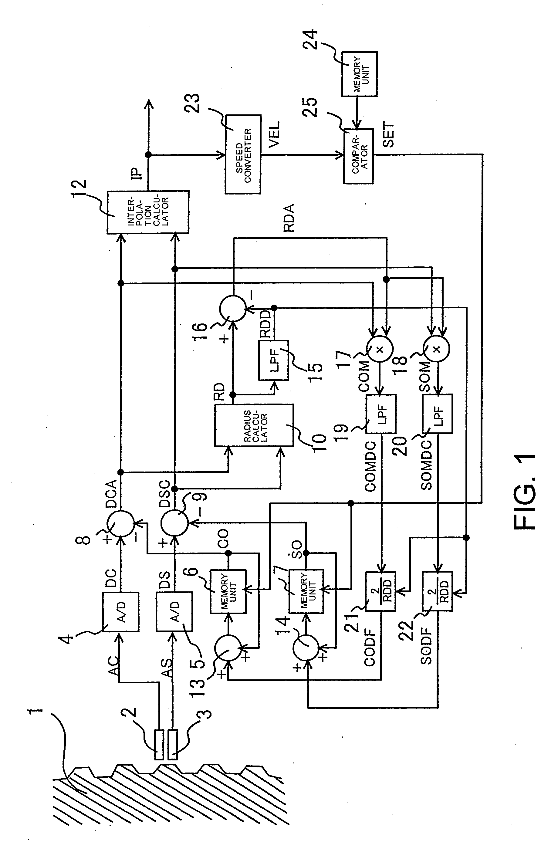
[0018]A first embodiment of the present invention will be described below with reference to the drawings. FIG. 1 is a block diagram showing a structure of a position detector according to the first embodiment of the present invention. In FIG. 1, elements having the same functions as those shown in FIG. 4 are denoted by the same reference numerals, and their description is not repeated.
[0019]As shown in FIG. 1, analog signals AC and AS output from two types of detection coils 2 and 3 are converted by A / D converters 4 and 5 into digital signals DC and DS. Signals DCA and DSC obtained by subtracting offset components CO and SO measured at the time of manufacture from the digital signals DC and DS using subtractors 8 and 9 are input to a radius calculator 10. The radius calculator performs a calculation according to the equation (1) to output a radius value RD.
[0020]The radius value RD output from the radius calculator 10 is input to a low-pass filter (LPF) 15, and a signal RDD which is...
second embodiment
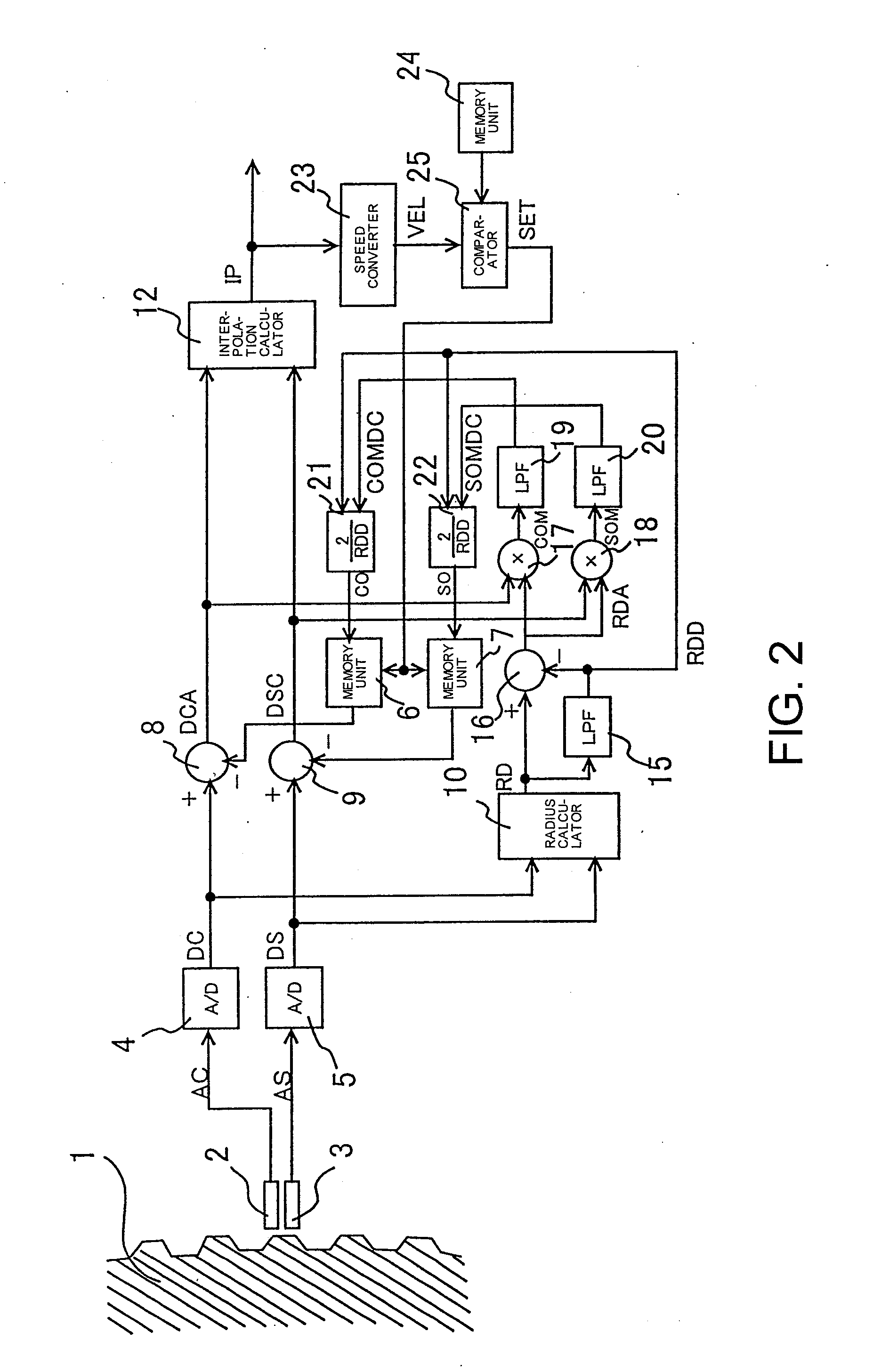
[0024]Next, a second embodiment will be described. FIG. 2 is a diagram showing a structure of a position detector according to the second embodiment. Although, in the first embodiment, the signals DCA and DSC in which offset components have been eliminated are used as inputs to the radius calculator 10, the signals DC and DS in which offset components have not been eliminated are used as inputs to the radius calculator 10 in the present embodiment, as shown in FIG. 2. In this case, because values output from the calculators 21 and 22 are offset components CO and SO of the signals DC and DS, adders 13 and 14 as shown in FIG. 1 are unnecessary. However, in this structure, there is a possibility that, when offset components included in the position sensor output signals are large, the offset identification accuracy may decrease.
third embodiment
[0025]Next, a third embodiment will be described. FIG. 3 is a diagram showing a structure of a position detector according to the third embodiment. Although, in the first embodiment, the low-pass filters 19 and 20 are used as means for extracting DC components of the signals COM and SOM output from the multipliers 17 and 18, average values for a period of time during which the position sensor output signals change by one cycle are extracted as DC components in the third embodiment, as shown in FIG. 3.
[0026]More specifically, averaging processors 26 and 27 output signals ACOMDC and ASOMDC obtained by averaging m values for the signals COM and SOM output from the multipliers 17 and 18 each time an interpolation value IP output from the interpolation calculator 12 changes by λ / m (λ represents an amount of movement for one pitch of the rotor 1, and m represents an integer greater than or equal to 2). The signals ACOMDC and ASOMDC are DC components of the signals COM and SOM. The calcula...
PUM
 Abstract
Description
Claims
Application Information
 - R&D
- Intellectual Property
- Life Sciences
- Materials
- Tech Scout
- Unparalleled Data Quality
- Higher Quality Content
- 60% Fewer Hallucinations
Browse by: Latest US Patents, China's latest patents, Technical Efficacy Thesaurus, Application Domain, Technology Topic, Popular Technical Reports.
© 2025 PatSnap. All rights reserved.Legal|Privacy policy|Modern Slavery Act Transparency Statement|Sitemap|About US| Contact US: help@patsnap.com


