Measuring arrangement and measuring method for measuring bearing clearance

a technology of bearing clearance and measuring arrangement, which is applied in the direction of mechanical measuring arrangement, measurement device, instrument, etc., can solve the problems of loss of comfort, control problem, or even loss of the rudder unit, and inability to measure the clearance of the bearing, so as to achieve the effect of repeatability of measurement and easy implementation

Inactive Publication Date: 2009-06-30
AIRBUS OPERATIONS GMBH
View PDF19 Cites 4 Cited by
  • Summary
  • Abstract
  • Description
  • Claims
  • Application Information

AI Technical Summary

Benefits of technology

[0009]It is, therefore, an object of the present invention to provide a measuring arrangement and / or a measuring method which allows a simple, reliable measurement of clearance of a bearing internal part relative to a bearing external part, in particular on control surfaces of an aircraft or spacecraft.

Problems solved by technology

Too much bearing clearance may result in, for example, vibrations, loss of comfort, control problems, or even loss of the rudder unit during the operation of the aircraft.
Such manual testing is very inaccurate.
As a result, for example, it may lead to premature replacement of bearings, which leads to high costs.
Alternatively, however, a faulty pivot bearing is not replaced and this results in control problems of the aircraft during operation.
A further difficulty is that, in principle, a plurality of the connecting arrangements shown in FIGS. 8 and 9 are provided concentrically above one another, said connecting arrangements connecting the rudder at a plurality of points to the rudder unit in an articulated manner.
For the mechanic, it is not possible simply by shaking to determine which of the plurality of pivot bearings has increased bearing clearance.
This leads, however, with regular maintenance work, to high costs and is only possible with specific, costly equipment.

Method used


Image

  • Measuring arrangement and measuring method for measuring bearing clearance
  • Measuring arrangement and measuring method for measuring bearing clearance
  • Measuring arrangement and measuring method for measuring bearing clearance

Examples


Embodiment Construction

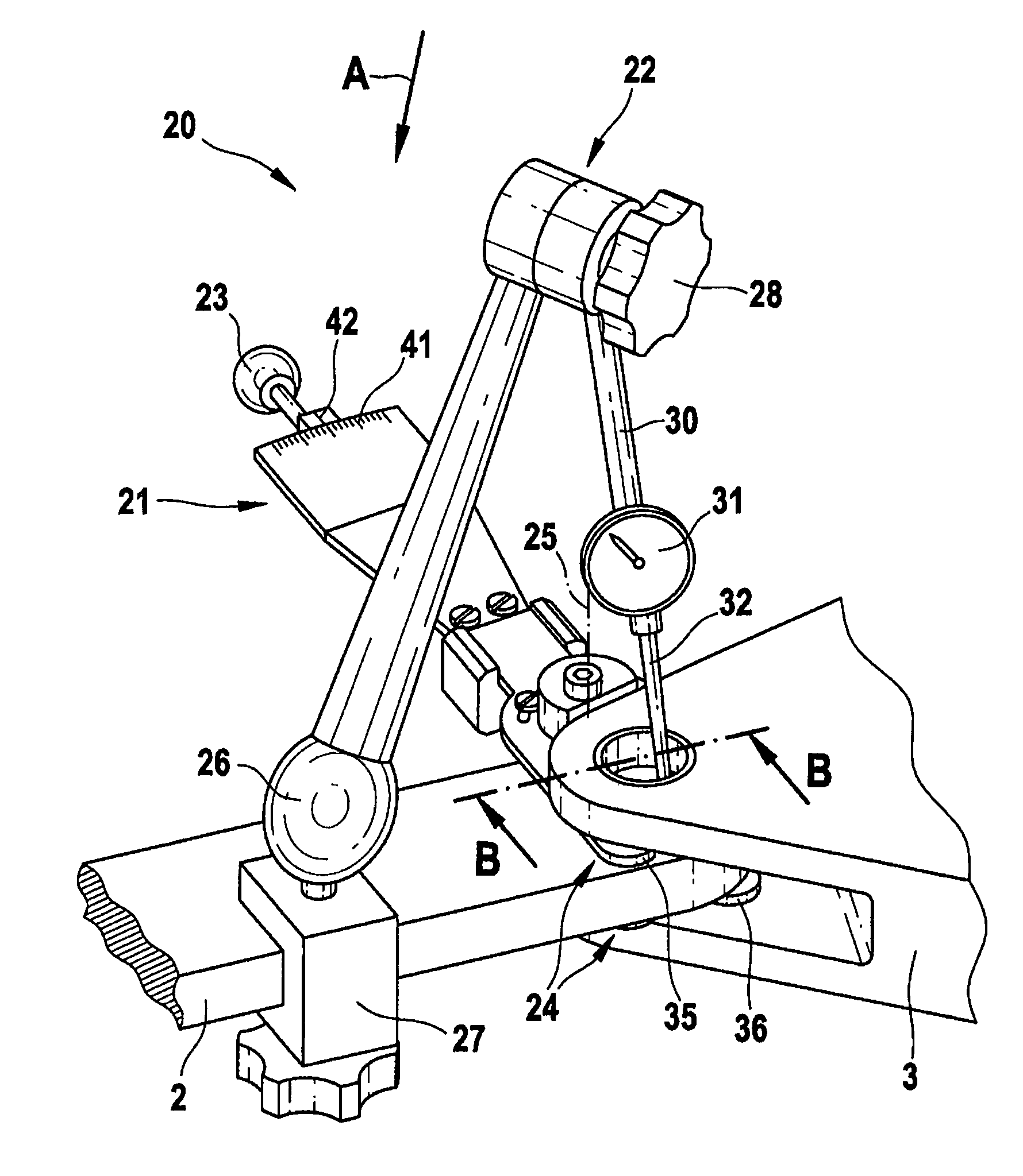
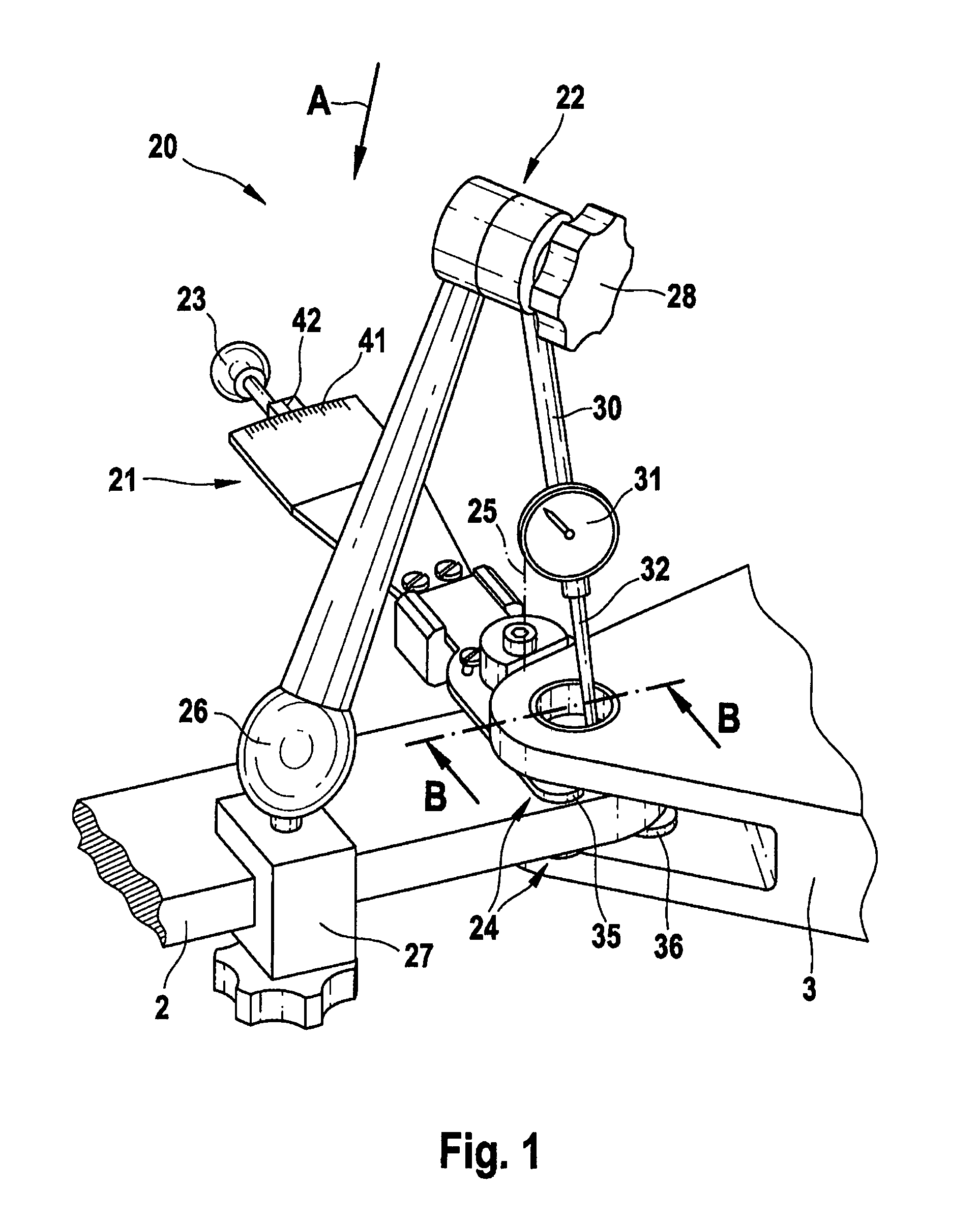
[0049]FIG. 1 shows in perspective the arrangement 1 already described in FIGS. 8 and 9, with the bearing fitting 2 and the bearing fork 3. A measuring arrangement 20 which comprises an adjusting device 21 and a measuring device 22, may also be seen.

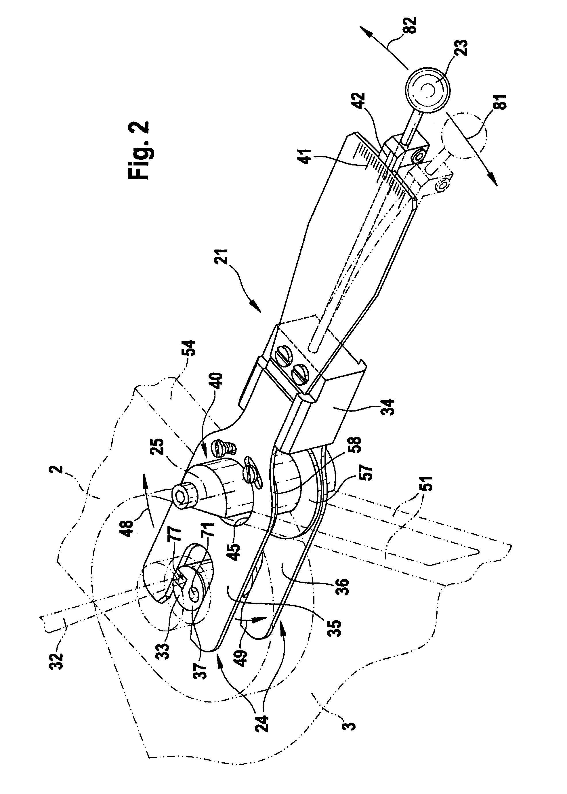
[0050]Before the attachment of the measuring arrangement 20, the bearing bolt 5 shown in FIGS. 8 and 9 may be replaced by a measuring bolt 33, shown by way of example in FIG. 2, the retaining means 9, 10 being removed.

[0051]The adjusting device 21 consists of a lever 23, by means of which an engagement means 24 fixedly connected thereto may be pivoted about a rotational axis 25 secured to the bearing fitting 2.

[0052]The measuring device 22 is preferably secured at its one end 26 by means of a clamping block 27 to the bearing fitting 2. At its other end 30, which may be pivotable about a pivot axis 28 which may be fixed relative to the one end 26, a dial gauge 31 is provided with a measuring sensor 32 which, as shown in FIG. 4, is in conta...


PUM


Abstract

A measuring arrangement for measuring clearance between a bearing internal part and a bearing external part of a bearing, in particular in an aircraft or spacecraft, is disclosed. The idea underlying the measuring arrangement is to adjust the bearing part relative to the bearing external part with an adjusting device and to measure the adjustment carried out with a measuring device. The advantage according to the measuring arrangement is that a much more accurate and repeatable measuring may be achieved relative to current measuring which depends on the intuition and experience of the mechanic.

Description

CROSS-REFERENCE TO RELATED APPLICATIONS[0001]This application claims the benefit of U.S. Provisional Application No. 60 / 853,608, filed Oct. 23, 2006 and German patent application No. 10 2006 058 903.3 filed Dec. 13, 2006, the entire disclosures of which are herein incorporated by reference.FIELD OF THE INVENTION[0002]The present invention relates to a measuring arrangement and a measuring method for measuring clearance between a bearing internal part and a bearing external part of a bearing, in particular in an aircraft or spacecraft.BACKGROUND OF THE INVENTION[0003]Although usable for any bearings, the present invention, as well as the problem underlying the invention, are explained in more detail with reference to a pivot bearing of an aircraft, which connects a rudder unit to a rudder in an articulated manner.[0004]An example of such a pivot bearing known to the applicant is shown in FIG. 8 in a perspective view and in FIG. 9 in a perspective sectional view C-C of FIG. 8.[0005]A ...

Claims


Application Information

Patent Timeline
Patent Type & Authority Patents(United States)
IPC IPC(8): G01B5/14G01D21/00
CPCG01B5/146
Inventor NILSSON, PERTHOMAS, ANDREKAMMLOTT, ANDREAS
Owner AIRBUS OPERATIONS GMBH
Why Eureka
Try Eureka