Device for indicating fuel filter clogging in internal combustion engines, particularly diesel engines

a fuel filter and internal combustion engine technology, applied in the direction of filtration separation, separation process, instruments, etc., can solve the problems of clogging time not constant, seat structure considerably complicating construction, and the clogging time cannot be taken as a parameter for the regular replacement of the cartridge, so as to achieve easy and quick adjustment

Inactive Publication Date: 2009-06-30
UFI FILTERS SPA
View PDF12 Cites 5 Cited by
  • Summary
  • Abstract
  • Description
  • Claims
  • Application Information

AI Technical Summary

Benefits of technology

[0011]The object of the present invention is to overcome the stated drawbacks within the context of a simple, rational and low-cost solution.
[0013]In particular, the invention provides a device for indicating clogging of the fuel filter of internal combustion engines, comprising a pressure sensor means sensing the difference between the entry and exit fuel pressure and housed within the filter casing, and a means for generating a signal proportional to said pressure difference which is located outside the filter casing and is not mechanically connected to the pressure sensor means. By virtue of this solution, a device according to the invention does not induce sealing problems, is of simple installation and replacement, and is of low cost.
[0017]By this solution, the invention handles an analogue signal, hence allowing continuous monitoring of the state of the filter, and does not merely indicate when clogging has taken place, as in the case of known devices. Moreover, when necessary, the acceptable limiting value of the pressure difference can be easily and quickly adjusted by acting merely on the electronic parameters of the device.

Problems solved by technology

In retaining said impurities, said cartridge progressively clogs and has therefore to be periodically replaced.
However, said clogging does not always take place gradually, hence the clogging time is not constant and cannot be taken as a parameter for the regular replacement of the cartridge.
However this configuration presents certain drawbacks: firstly, problems in sealing the filter against the external environment inevitably arise at the fixing between the seat and the device; in addition, the provision of said seats considerably complicates construction, while the presence of the gaskets makes it more difficult to mount and replace the device.
Finally, these factors also produce a cost increase that cannot be ignored.

Method used


Image

  • Device for indicating fuel filter clogging in internal combustion engines, particularly diesel engines
  • Device for indicating fuel filter clogging in internal combustion engines, particularly diesel engines
  • Device for indicating fuel filter clogging in internal combustion engines, particularly diesel engines

Examples


Embodiment Construction

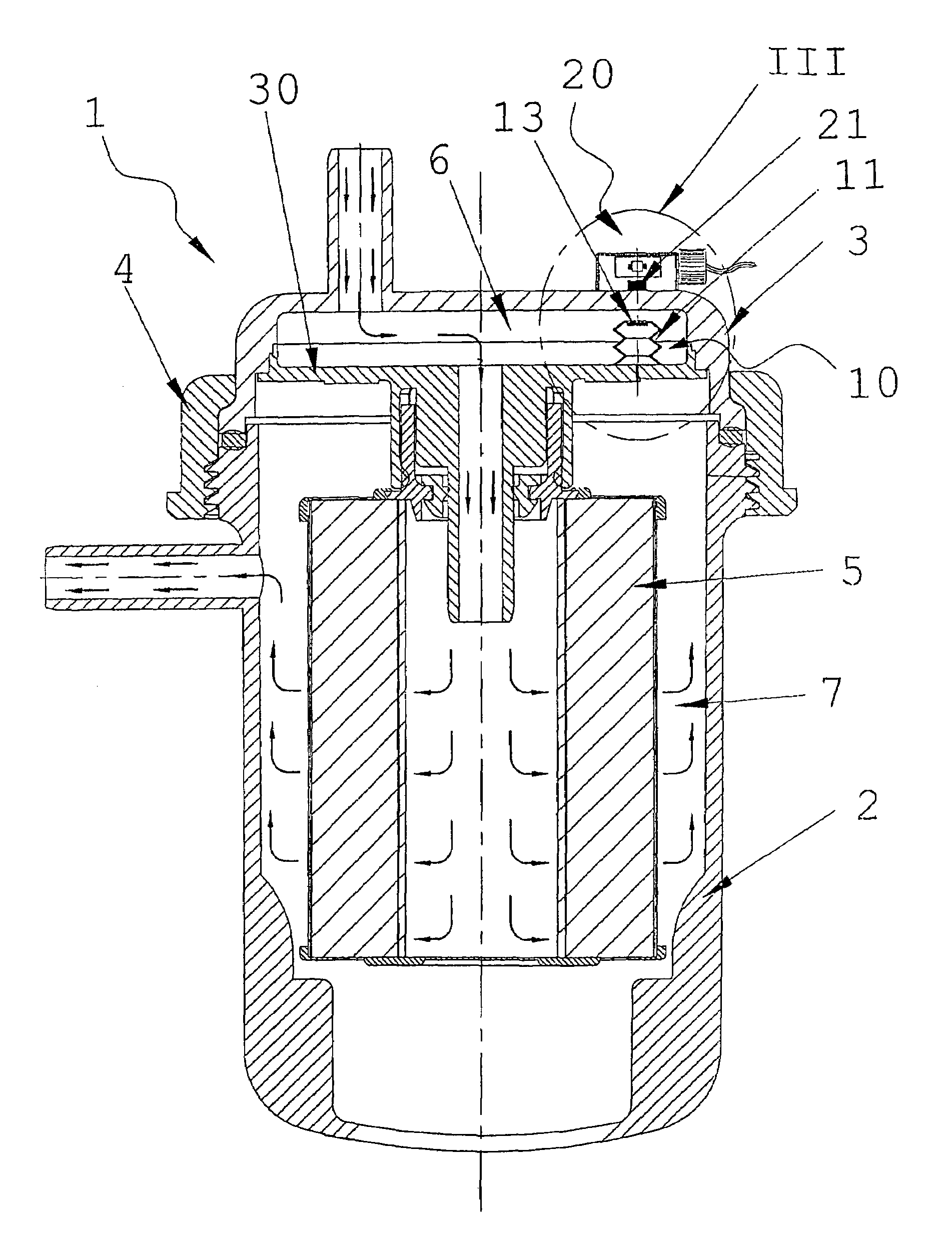
[0022]Said figures, and in particular FIG. 1, show a diesel fuel filter for installation on a diesel engine.

[0023]Said filter, indicated by the reference numeral 1, comprises a cup-shaped outer casing 2, and an upper cover 3 of amagnetic material sealedly fixed to the casing by a ring nut 4.

[0024]Inside the casing 2 a disc 30 supports a filter cartridge 5 which divides the inner volume of the filter into two chambers, one 6 for the diesel fuel to be filtered, and the other 7 for the filtered diesel fuel, they being associated with an inlet conduit and an outlet conduit respectively.

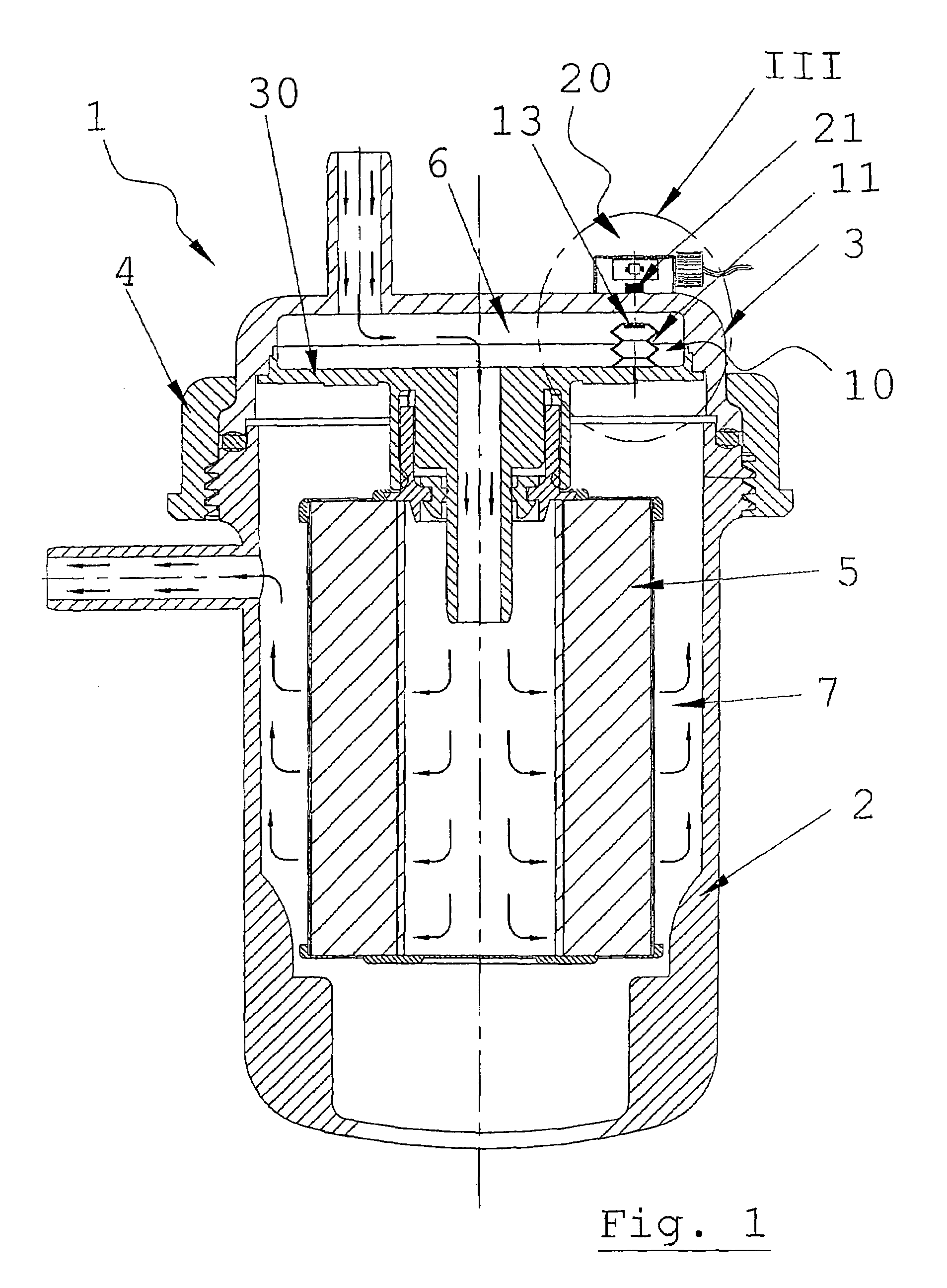
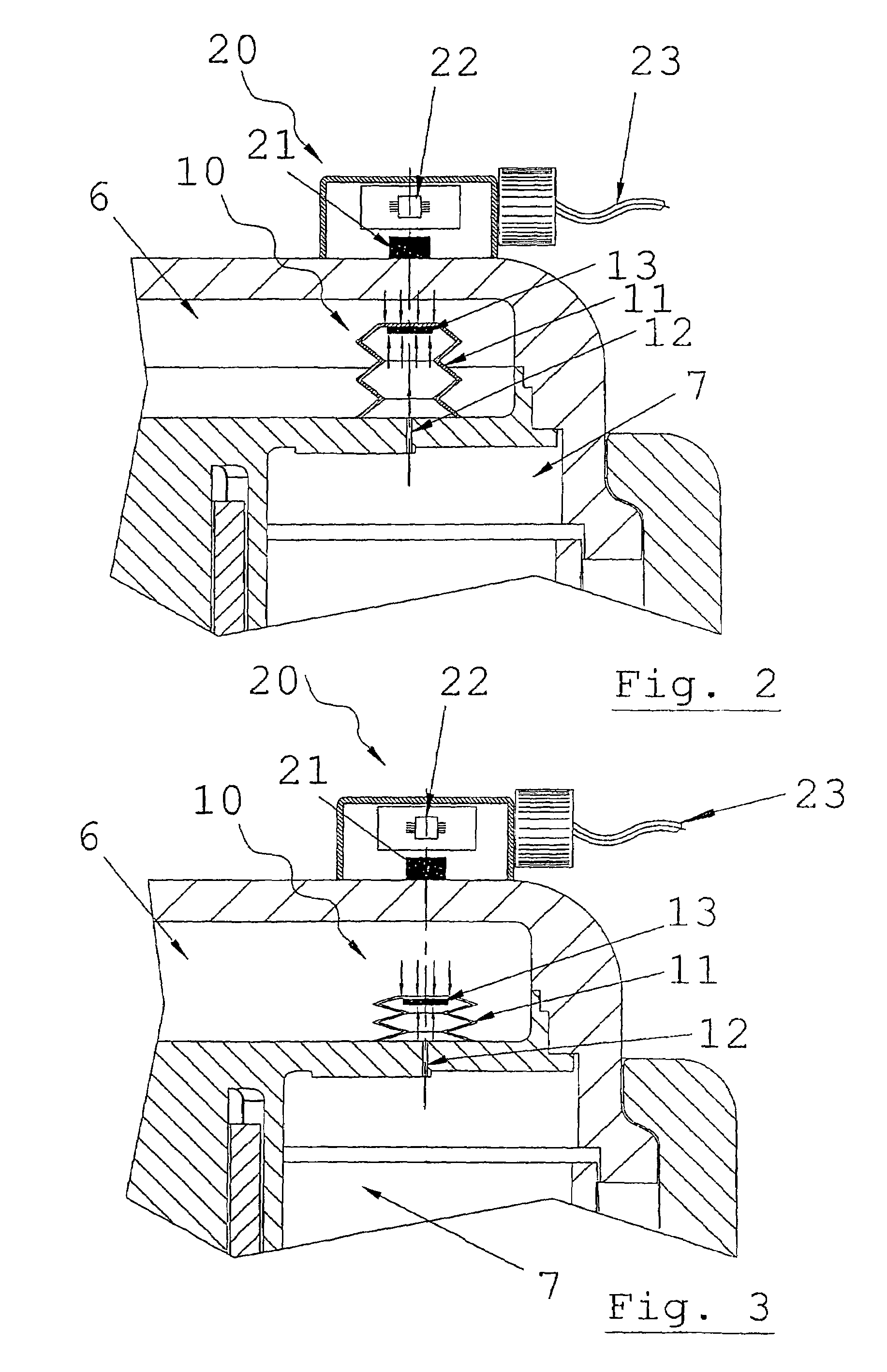
[0025]In the chamber 6 (see FIGS. 2 and 3) there is inserted a pressure sensor means 10, composed of an extendable membrane 11, a hole 12 which connects the volume on the inside of the membrane to the filtered diesel oil chamber 7, and a magnet 13 mounted on said membrane 11. The pressure sensor 10 is configured such that elongation or contraction of the membrane 11, and with it an axial movement of the m...


PUM

PropertyMeasurementUnit
pressureaaaaaaaaaa
volumeaaaaaaaaaa
elongationaaaaaaaaaa

Abstract

A device for indicating clogging of the fuel filter (1) of internal combustion engines, in particular diesel engines, the filter having an outer casing (2) closed by a cover (3) of amagnetic material, and a filter element (5) which, together with a disc (30) to which it is connected, defines two chambers (6and 7) for fuel entry and exit respectively; the device further includes a pressure sensor (10) sensing the difference between the entry and exit fuel pressure and housed inside the filter casing, and a sensor (21) for generating a signal proportional to the pressure difference which is located outside the filter casing and is not mechanically connected to the pressure sensor.

Description

TECHNICAL FIELD[0001]The present invention relates generally to a fuel filter for use in internal combustion engines, and more particularly in diesel engines.PRIOR ART[0002]Diesel fuel normally contains impurities, or more or less solid substances (especially paraffins) which separate at relatively low temperature.[0003]For this reason the engine feed system must be provided with a suitable filter able to clean the fuel.[0004]Modern diesel fuel filters generally consist of a cup-shaped outer casing and a closure cover. Said casing contains a coaxial filter cartridge of toroidal form which, when fixed to a connection disc, separates the internal volume of the cup into an entry chamber and an exit chamber for the fuel.[0005]In retaining said impurities, said cartridge progressively clogs and has therefore to be periodically replaced.[0006]However, said clogging does not always take place gradually, hence the clogging time is not constant and cannot be taken as a parameter for the regu...

Claims


Application Information

Patent Timeline
Patent Type & Authority Patents(United States)
IPC IPC(8): G01M15/09B01D35/143F02M37/40
CPCB01D35/143F02M37/22B01D29/606B01D29/232F02M37/40F02M37/32
Inventor GIRONDI, GIORGIO
Owner UFI FILTERS SPA
Why Eureka
Try Eureka