
Device for Indicating Fuel Filter Clogging in Internal Combustion Engines, Particularly Diesel Engines
a fuel filter and internal combustion engine technology, applied in the direction of filtration separation, separation process, instruments, etc., can solve the problems of clogging time not constant, seat structure considerably complicating construction, and the clogging time cannot be taken as a parameter for the regular replacement of the cartridge, so as to achieve easy and quick adjustment
- Summary
- Abstract
- Description
- Claims
- Application Information
AI Technical Summary
Benefits of technology
Problems solved by technology
Method used
Image

Examples
Embodiment Construction
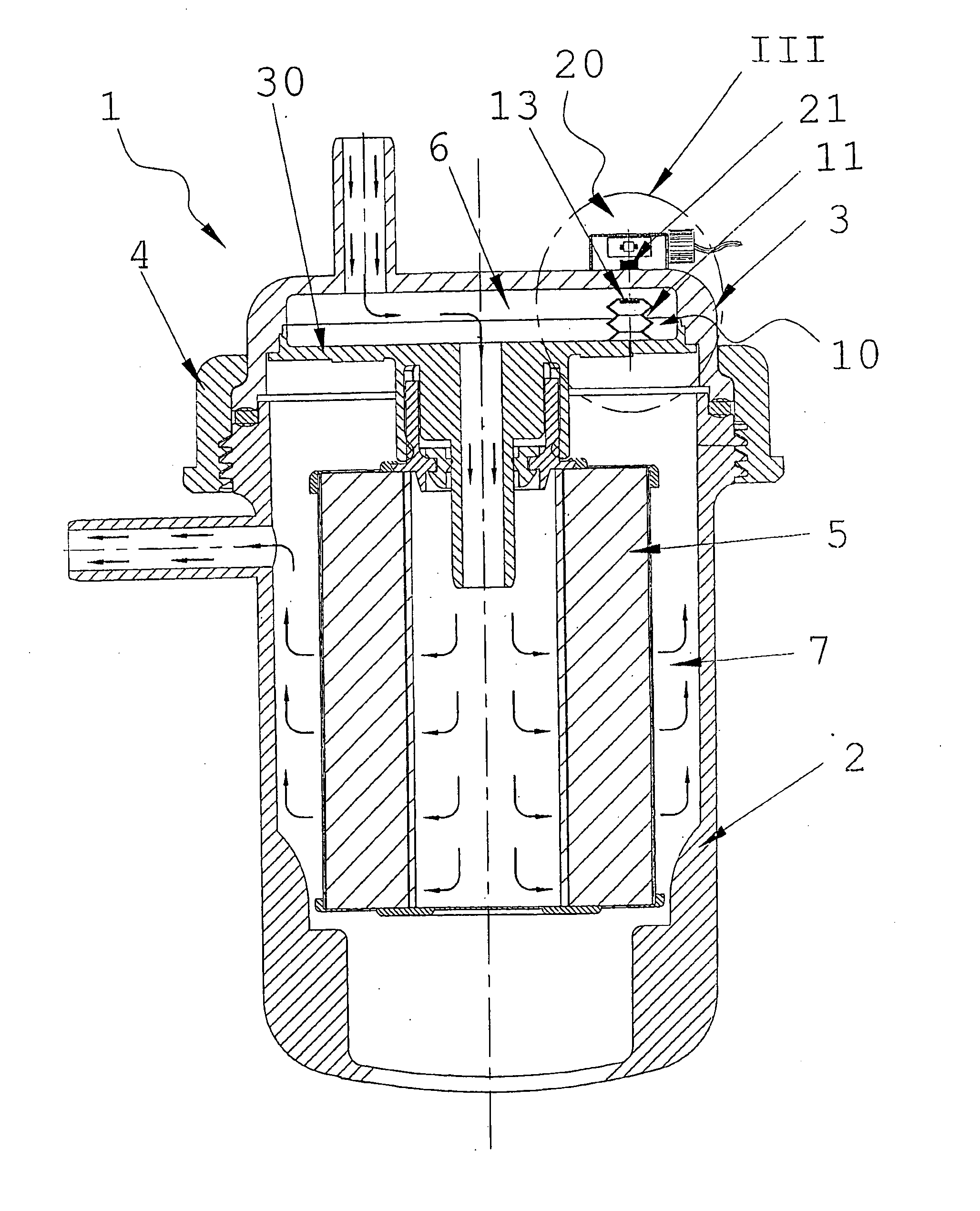
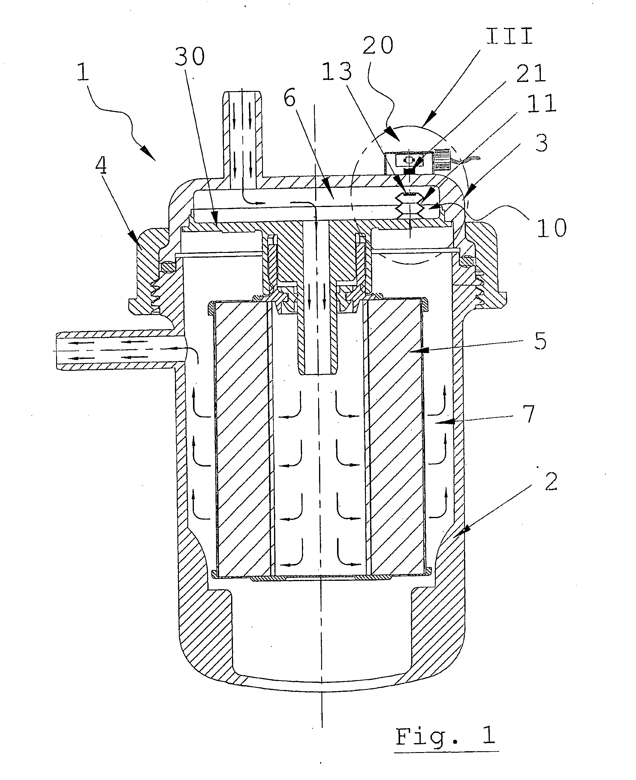
[0022]Said figures, and in particular FIG. 1, show a diesel fuel filter for installation on a diesel engine.
[0023]Said filter, indicated by the reference numeral 1, comprises a cup-shaped outer casing 2, and an upper cover 3 of amagnetic material sealedly fixed to the casing by a ring nut 4.
[0024]Inside the casing 2 a disc 30 supports a filter cartridge 5 which divides the inner volume of the filter into two chambers, one 6 for the diesel fuel to be filtered, and the other 7 for the filtered diesel fuel, they being associated with an inlet conduit and an outlet conduit respectively.
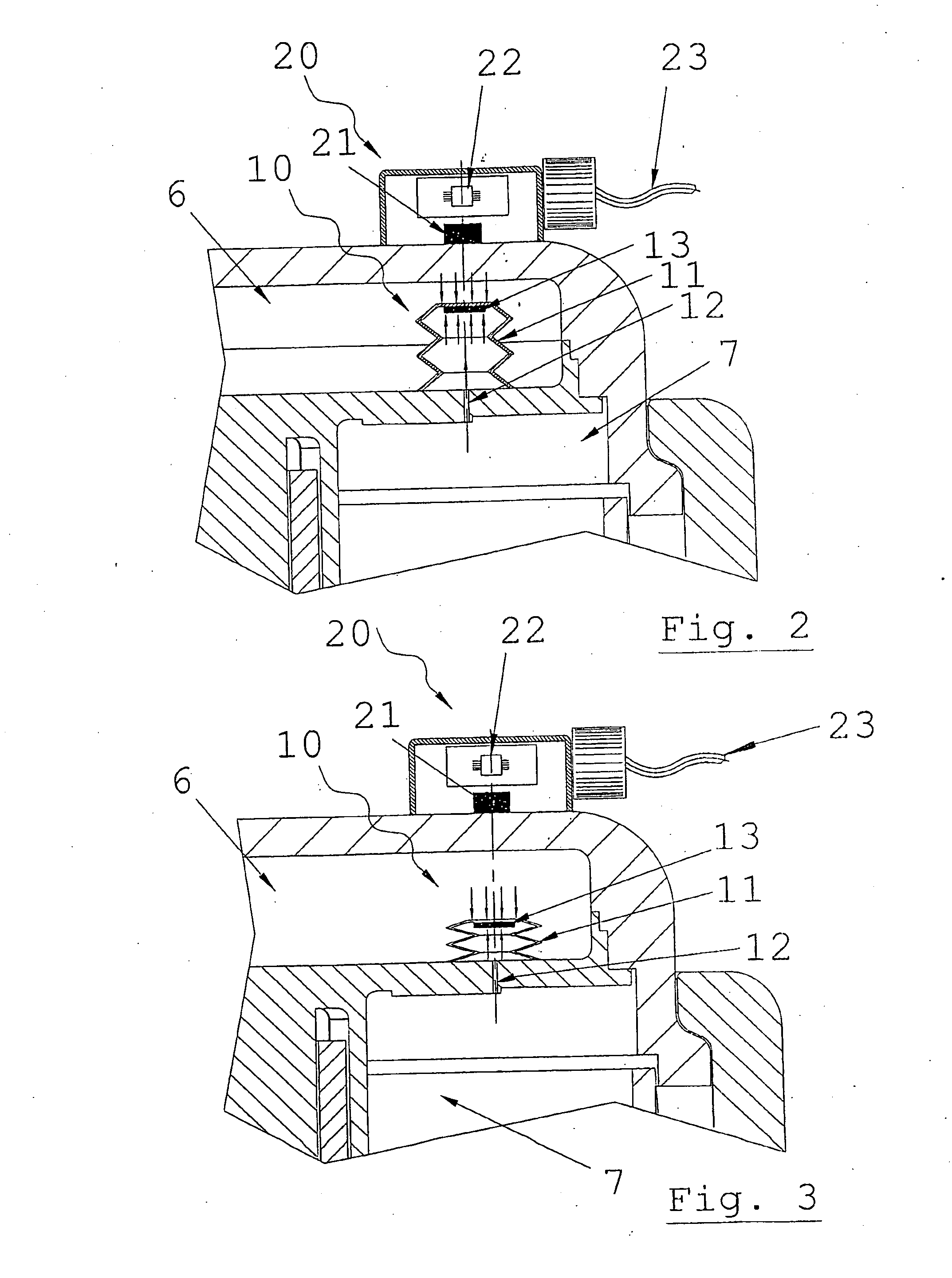
[0025]In the chamber 6 (see FIGS. 2 and 3) there is inserted a pressure sensor means 10, composed of an extendable membrane 11, a hole 12 which connects the volume on the inside of the membrane to the filtered diesel oil chamber 7, and a magnet 13 mounted on said membrane 11. The pressure sensor 10 is configured such that elongation or contraction of the membrane 11, and with it an axial movement of the m...
PUM
| Property | Measurement | Unit |
|---|---|---|
| Thickness | aaaaa | aaaaa |
| Pressure | aaaaa | aaaaa |
| Magnetic field | aaaaa | aaaaa |
Abstract
Description
Claims
Application Information