Flexible solar roofing modules

a solar array and flexible technology, applied in the field of photovoltaic arrays, can solve the problems of time and complexity of solar array installation, limiting the adoption of solar technology, dissonance between the age of the existing roof and the solar system, etc., and achieves the effect of reducing installation costs and simplifying installation

Active Publication Date: 2020-09-29
TESLA INC
View PDF36 Cites 0 Cited by
  • Summary
  • Abstract
  • Description
  • Claims
  • Application Information

AI Technical Summary

Benefits of technology

[0007]Various embodiments provide a new and improved approach to installing solar on new roofs and existing roofs, and in particular, presenting a roof that appears to be a tile roof. Some aspects fit over an existing tile roof and / or other suitable roof surfaces (e.g., a metal roof, composite shingle, roof deck, underlayment or insulation layer). In particular, aspects of the roofing installation are modular and flexible, which simplifies installation as well as replacement of individual photovoltaic modules of the system. In addition, some aspects cost less to make and install compared to conventional solar systems. Further, some arrangements of photovoltaic portions (and / or non-photovoltaic portions) of modules can generate a visual pattern and aesthetic that appears consistent with traditional roofing materials. Some solar systems can be installed as a new roof rather than a re-roof or mounted to an existing roof. These and other embodiments are discussed in greater detail in the detailed description and drawing figures.

Problems solved by technology

One factor that may limit the adoption of solar technology is aesthetics.
Further, the time and complexity of a solar array installation can be an obstacle to the adoption of solar technology.
Another obstacle to solar adoption in existing homes is the dissonance between the age of the existing roof and the solar system, particularly where the existing roof is made from composition shingles.
So the customer may be presented with the dilemma of getting a new roof first, increasing the cost of going solar, or installing a 25-year solar system on a roof which may have a relatively shorter remaining operational lifespan.

Method used


Image

  • Flexible solar roofing modules
  • Flexible solar roofing modules
  • Flexible solar roofing modules

Examples


Embodiment Construction

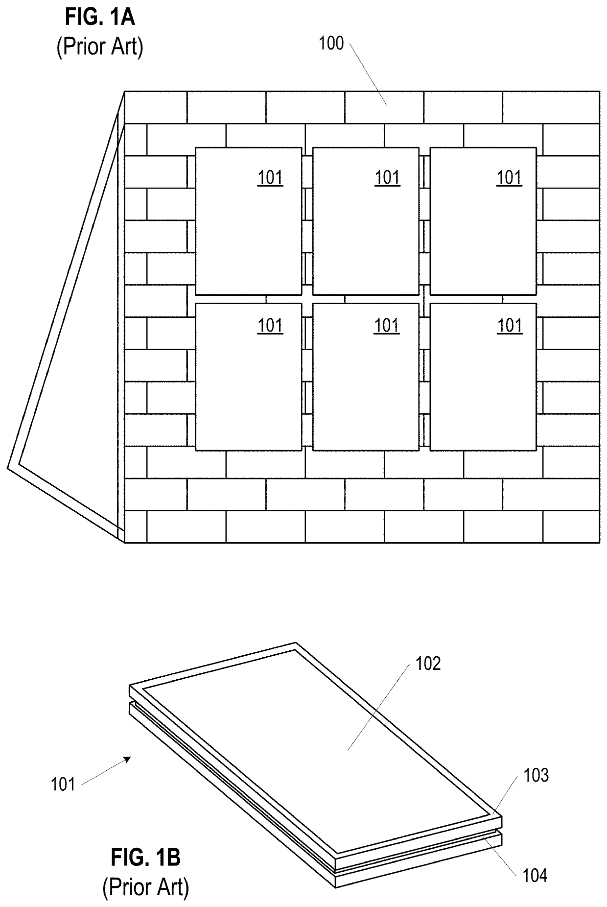
[0034]The present disclosure describes various embodiments of photovoltaic roofing systems and associated systems and methods, and in particular building integrated photovoltaic roofing systems. Some embodiments relate to building integrated photovoltaic module assemblies and associated systems and methods. In various embodiments, the systems described herein lower costs of conventional systems in which a photovoltaic (“PV”) system is installed over a roof, and at the same time can provide an improved aesthetic for a PV roof system, and particularly for a building integrated photovoltaic (“BIPV”) system.

[0035]Certain details are set forth in the following description and in the Figures to provide a thorough understanding of various embodiments of the present technology. Other details describing well-known structures and systems often associated with PV systems, roofs, etc., however, are not set forth below to avoid unnecessarily obscuring the description of the various embodiments o...


PUM


Abstract

Building integrated photovoltaic (BIPV) systems provide for solar panel arrays that can be aesthetically pleasing to an observer. BIPV systems can be incorporated as part of roof surfaces as built into the structure of the roof, particularly as roofing modules that have photovoltaic elements embedded or incorporated into the body of the module, in distinct tiles-sized areas. The use of modules that replicate the look of individual roofing tiles (or shingles) can lead to a more efficient installation process. Further, modules can include flexible joints between the distinct tiles-sized areas, across which solar cells within the module are electrically connected. The flexibility granted to the modules also makes installation easier, and further improves the fatigue and strain resistance of the overall solar array for its operational life.

Description

TECHNICAL FIELD[0001]This generally relates to photovoltaic arrays.BACKGROUND[0002]Solar is becoming increasingly popular in the United States and abroad, but penetration remains relatively low versus the number of homes that could benefit from solar. The price per kilowatt for solar is now competitive with or below that of fossil fuel-based utility power in most areas, however, solar largely remains a niche product for those who value saving money, reducing CO2 emissions, or both.[0003]One factor that may limit the adoption of solar technology is aesthetics. Most residential solar systems are installed as modules over an existing tile or composition shingle roof. The solar array, which often only covers a portion of the roof, or even a portion of one mounting plane of the roof, stands out as separate and distinct from the existing roof, both in height and material. This difference is therefore visible from the street level and even over large distances.[0004]Further, the time and c...

Claims


Application Information

Patent Timeline
Patent Type & Authority Patents(United States)
IPC IPC(8): H02S20/23H01L31/02F24S25/35H02S40/36H02S20/25H02S30/10H01L31/05H01L31/042F24S20/00
CPCH02S30/10H01L31/0504H01L31/0201H02S20/23H02S40/36F24S25/35H02S20/25H01L31/042Y02B10/10Y02E10/47F24S2020/10Y02B10/20Y02E10/50Y02A30/60
Inventor ATCHLEY, BRIAN EDWARDMEISEL, ANDREASFLANIGAN, DANIEL PRESTONHUDSON, TYRUS HAWKES
Owner TESLA INC
Why Eureka
Try Eureka