Machine mounting system

a technology for mounting systems and machines, applied in the direction of shock absorbers, power plants being motor-driven, vessel construction, etc., can solve the problems of inadequate mounting, fatalities, and inability to meet the requirements of onshore applications, and achieve the effect of avoiding damage, avoiding damage, and avoiding damag

Inactive Publication Date: 2009-06-30
SOLAR TURBINES +1
View PDF20 Cites 140 Cited by
  • Summary
  • Abstract
  • Description
  • Claims
  • Application Information

AI Technical Summary

Problems solved by technology

Due to such torsional motion, however, four-point mounting systems for onshore applications are typically not ideal for offshore systems.
Twisting of a vessel's deck can cause the mounting points of a four-point system to actually move out of the originally intended mounting plane.
For equipment having a low tolerance for misalignment of components, inadequate mounting can be fatal.
This approach, however, has drawbacks of its own.
While the design of Bender et al. certainly has useful applications, it appears to be engineered for a specific engine type, and thus suffers from lack of flexibility in its applications.

Method used


Image

  • Machine mounting system
  • Machine mounting system
  • Machine mounting system

Examples


Embodiment Construction

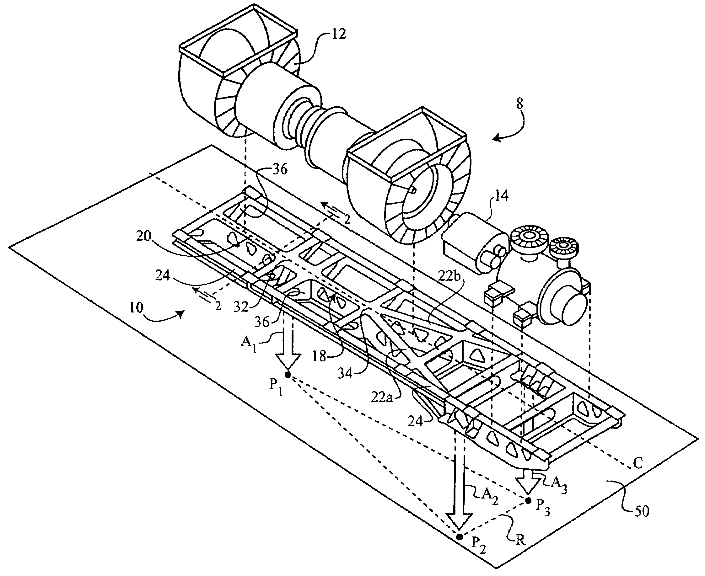
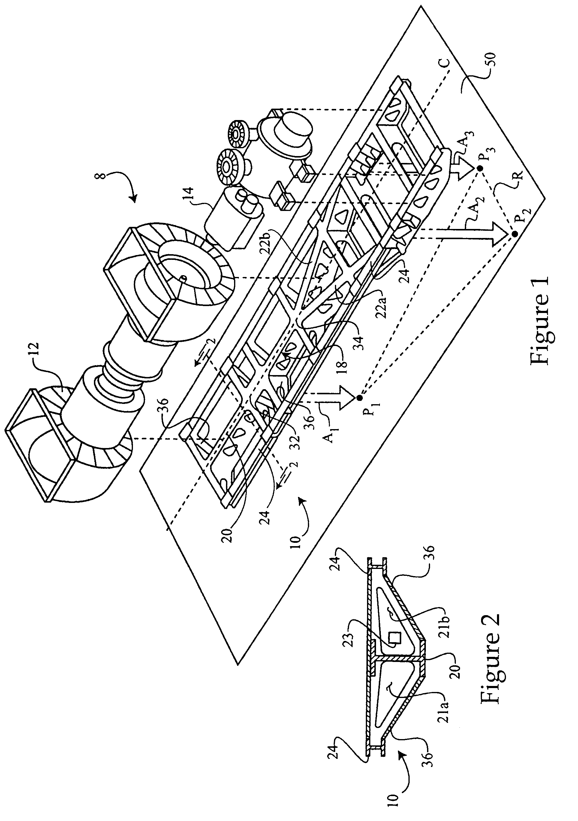
[0017]Referring to FIG. 1, there is shown an engine assembly 8, which may be a gas turbine engine assembly, according to the present disclosure. Assembly 8 includes a gas turbine engine driver component 12 and a driven component 14, such as a compressor and gearbox having a rectangular mounting configuration. Driver component 12 and driven component 14 may be coupled with a machine mounting frame 10. Frame 10 includes first and second beams 22a and 22b joined in a V-configuration and defining a predetermined three-point load path, illustrated with vector arrows A1, A2 and A3 in FIG. 1.

[0018]Frame 10 may further be mounted to a mounting platform 50, such as a marine vessel body, via mounting members (not shown in FIG. 1) positioned at points P1, P2 and P3, defining a mounting plane R which is oriented parallel to beams 22a and 22b. When platform 50 experiences torsional stresses, points P1, P2 and P3 remain substantially within a common plane, although this plane may actually differ ...


PUM


Abstract

A gas turbine engine assembly includes a gas turbine engine mounted on a three-point mounting frame. The three-point mounting frame includes an engine support structure having first and second beams in a V-configuration, and a secondary support structure that is positioned about the engine support structure and has a rectangular footprint. The frame may include a Y-configuration that includes the V-configuration, and may be implemented in a machine mounting system, such as in a marine vessel.

Description

TECHNICAL FIELD[0001]The present disclosure relates generally to mounting apparatuses for Machines, such as gas turbine engines, and relates more particularly to a three-point Frame with first and second beams joined in a V-configuration.BACKGROUND[0002]Specialized mounting systems have been necessary for machines and all manner of mechanical devices since the dawn of the industrial era. It has been found that for relatively large, bulky machines such as certain engines, mounting systems must often be developed which can provide robust support and stability to the machine, while being tailored to specific machine designs. Mounting strategies often must further account for the environments in which a particular machine will operate.[0003]The marine industry provides a number of examples of particular operating environments requiring specialized machine mounting systems to properly support large, heavy machines. This is due at least in part to the motion and vibrations typically exper...

Claims


Application Information

Patent Timeline
Patent Type & Authority Patents(United States)
IPC IPC(8): F16M1/00
CPCB63H21/16B63H21/30F01D15/04F01D25/28F16M5/00
Inventor DUNN, JEFFREY H.BROWN, IAN T.
Owner SOLAR TURBINES
Why Eureka
Try Eureka