

Magnetorheological hydraulic engine mount based on extrusion mode
A technology of hydraulic suspension and extrusion mode, which is applied in the direction of vibration suppression adjustment, non-rotational vibration suppression, etc., can solve the problems of poor adjustable range of damping force, high-frequency dynamic hardening, etc., so as to improve vibration isolation ability and avoid magnetic Road coupling, increase the effect of adjustable range
- Summary
- Abstract
- Description
- Claims
- Application Information
AI Technical Summary
Problems solved by technology
Method used
Image

Examples
Embodiment 1
[0039] Embodiment 1 A magneto-rheological hydraulic mount for an engine with a double-excitation pole plate structure
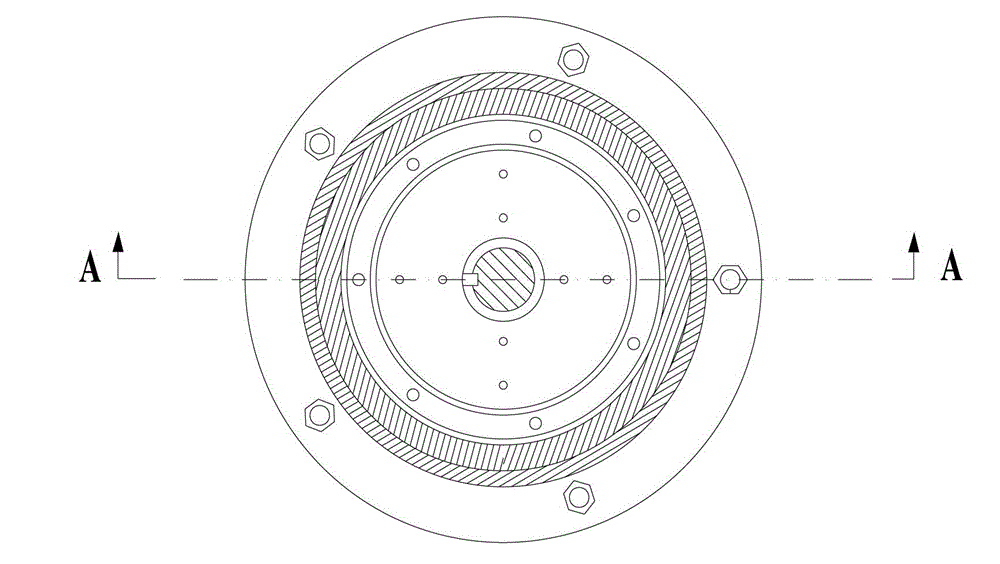
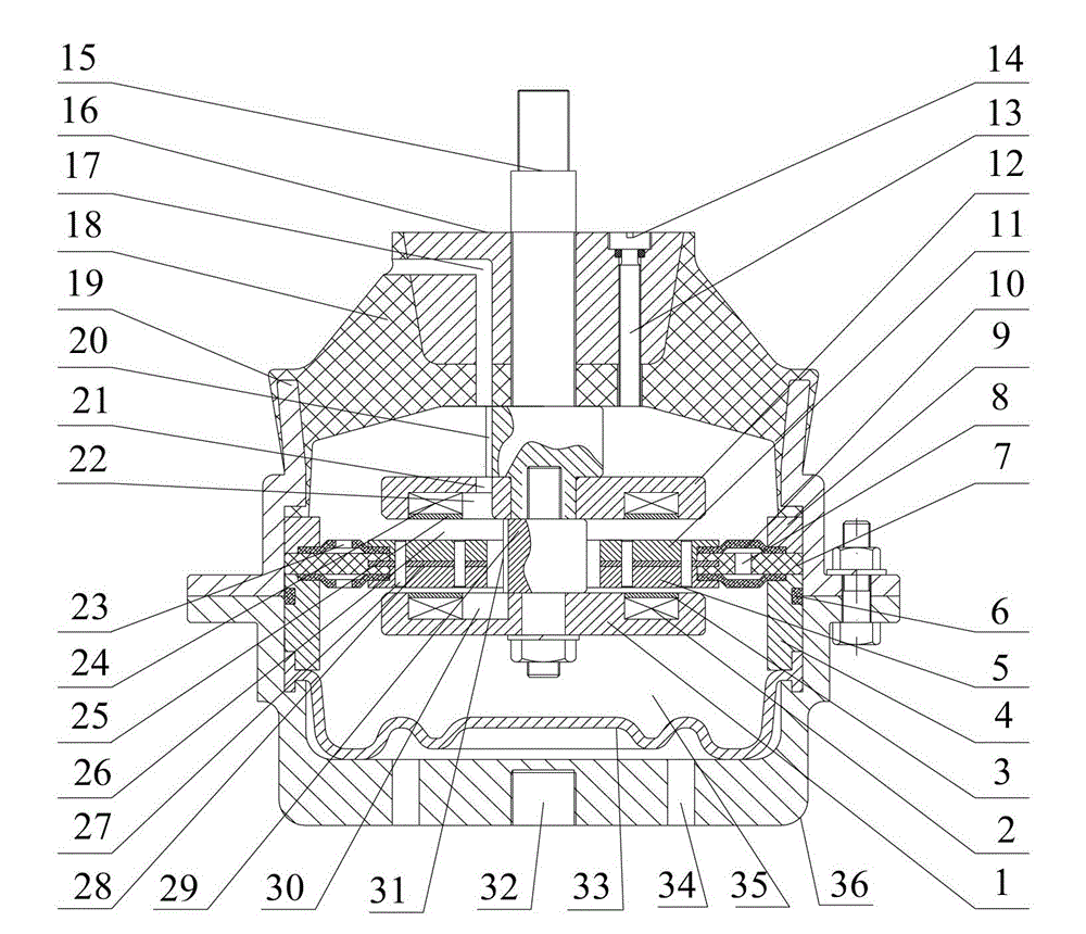
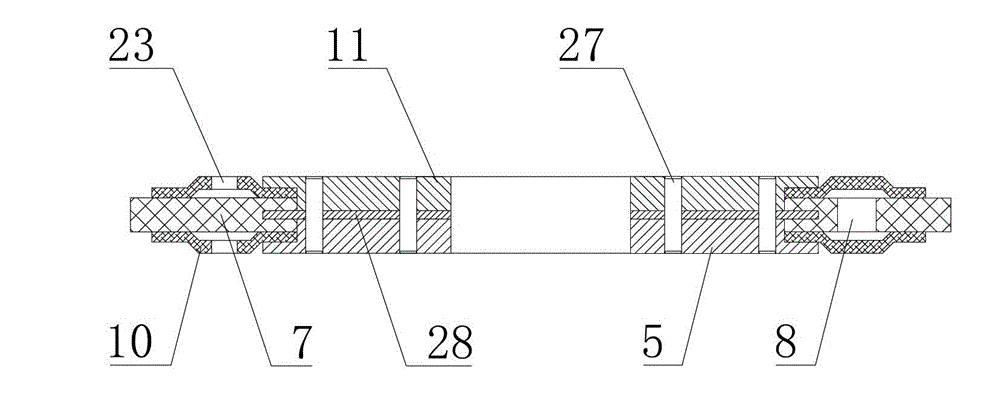
[0040] Specifically, such as Figure 1-5 As shown, the upper and lower chambers separated by the decoupler are each provided with an excitation pole plate; the upper and lower sides of the decoupler are respectively provided with a Squeeze the pole plate, between the exciter pole plate 12 and the extrude pole plate 11 in the upper chamber and between the exciter pole plate 1 and the extrude pole plate 5 in the lower chamber respectively form a squeeze damping aisle. A magnetic isolation material 28 is provided between the extruded pole plates located on the upper and lower sides of the decoupler to avoid coupling of the internal magnetic circuits of the upper and lower extruded damping channels; the overload protection rubber block 7 is in contact with the magnetic isolation The material 28 is vulcanized together and installed between the upper and lower de...
Embodiment 2
[0043] Embodiment 2 An engine magnetorheological hydraulic mount with a single excitation pole plate structure
[0044] As an alternative to Example 1, such as Figure 6 As shown, the middle part of the decoupler is provided with a second chamber 37 filled with magnetorheological fluid, the top and bottom of the second chamber 37 are formed by the extruded pole plate, and the excitation pole plate 38 Set inside the second chamber 37, the extruded pole plate at the top of the second chamber 37 is provided with a through hole, and the connecting rod 15 extends from the through hole to the inside of the second chamber 37 and The field pole plate 38 is fixedly connected. An extrusion damping channel is formed between the upper and lower surfaces of the excitation pole plate, the extrusion pole plate 39 at the top of the second chamber 37 and the extrusion pole plate 40 at the bottom. The outer edges of the overload protection rubber block 7 and the upper and lower decoupling mem...
Embodiment 3
[0046] Embodiment 3 Another magneto-rheological hydraulic mount for an engine with a single-excitation pole plate structure
[0047] As an alternative to Example 1 or 2, such as Figure 8 As shown, the middle part of the decoupler is fixedly provided with an excitation pole plate 43, and the middle part of the excitation pole plate 43 is provided with a through hole allowing the connecting rod 15 to pass therethrough; the upper and lower parts separated by the decoupler Each of the two chambers is provided with an extruded pole plate 44, 45, between the extruded pole plate 44 on the upper part of the decoupler and the excitation pole plate 43, the extruded pole plate 45 on the lower part of the decoupler and the An extrusion damping channel filled with magnetorheological fluid is formed between the excitation pole plates 43; the upper and lower extrusion pole plates 44, 45 are fixedly connected to the connecting rod 15; the decoupler includes overload protection Rubber blocks...
PUM
 Abstract
Description
Claims
Application Information