Door arrester

a technology for arresters and doors, applied in the field of door arresters, can solve the problems of undesirable fluctuations in the retaining force of door arresters, high manufacturing costs, and high cost of sheet metal blank manufacturing, and achieve the effect of effective damping and even more deformation

Inactive Publication Date: 2009-06-30
EDSCHA ENG GMBH
View PDF43 Cites 27 Cited by
  • Summary
  • Abstract
  • Description
  • Claims
  • Application Information

AI Technical Summary

Benefits of technology

[0012]It is an object of the invention to provide a door arrester which permits a motor vehicle door to be arrested in an inexpensive and reliable manner.

Problems solved by technology

The known door arrester has a series of deficiencies, in particular, the outlay on installation and the multiplicity of parts are responsible for high manufacturing costs.
The geometry of the holder housing is complex, since a multiplicity of parts have to be provided on it, which means that the manufacturing of the corresponding sheet-metal blanks involves correspondingly high costs.
The insertion and fixing of the studs forming pivot axes of the cage and the loading roll and the abutment roll requires the provision, which is complex in terms of manufacturing, of holes and elongated slots in the sheet-metal blank and problems to do with tolerances mean that these result in undesirable fluctuations in the retaining forces of the door arresters.
Furthermore, the rollers, when their ability to roll diminishes, produce annoying squeaking noises which are undesirable and which at the same time result in increased wear to the roller and retaining bar, since the parts are designed for rolling along each other and not for sliding.
The actuating resistance of the door arrester changes over its service life, as a result of which an arresting performance which is initially found to be pleasant is gradually found to be annoying.
The prestress of the torsion springs means that the parts have to be installed in a sequence in which first of all the door-retaining bar is inserted through a corresponding opening in the holder housing and then the stud is passed through the torsion spring and the cage, which means that the resultant installation unit can be difficult to handle when installing it in a motor vehicle.
The known door arrester is heavy and contributes to increasing the overall weight of the vehicle.
Finally, because of its unattractive external appearance and the components which are accessible from the outside and because of its sensitivity to corrosion, the known door arrester is fitted only on the inside of a door assembly part, which means that it is difficult to gain access to and the outlay on installation is considerable.
All in all, the production and installation of the known door arrester are complex and expensive.
The production and installation of the known door arrester are complex and expensive.
Furthermore, mating rolls of this type which are produced from a soft plastic have a tendency, due to the stress, to form grooves in the roll, and so in heavy doors regularly have to be replaced by metal rolls.
In order to obtain sufficient strength, metallically substrates are regularly required for soft plastics of this type thus involving an undesirable multiplicity of parts and materials.
An arrester of this type which brakes a lightweight object owing to the friction of the surfaces which are in contact cannot be used for heavy vehicle doors.
Also, the rubber-elastic profiled components do not meet the requirements made of the working life of a motor vehicle door arrester which has to withstand several thousand changes of load without a noticeable change in the retaining moments.
Moreover, the production and installation of arresters of this type which are to be composed of a large number of individual parts is time-consuming and costly.
A first disadvantage of the known door arrester is that the retaining forces differ in the opening direction and in the closing direction.
Furthermore, the retaining forces are entirely neutralized in the event of sudden changes of load, which may cause the vehicle door to suddenly swing out.
Finally, a pliable strut does not meet the requirements made of the working life of a motor vehicle door arrester which has to withstand several thousand changes of load without a noticeable change in the retaining moments.
Although the known door arrester permits uniform retention of the retaining bar in the opening direction as in the closing direction, it also holds true here that the requirements made of the working life of a motor vehicle door arrester, which has to withstand several thousand changes of load without a noticeable change in the retaining moments, are not met by the rubber bodies.

Method used


Image

  • Door arrester
  • Door arrester
  • Door arrester

Examples


Embodiment Construction

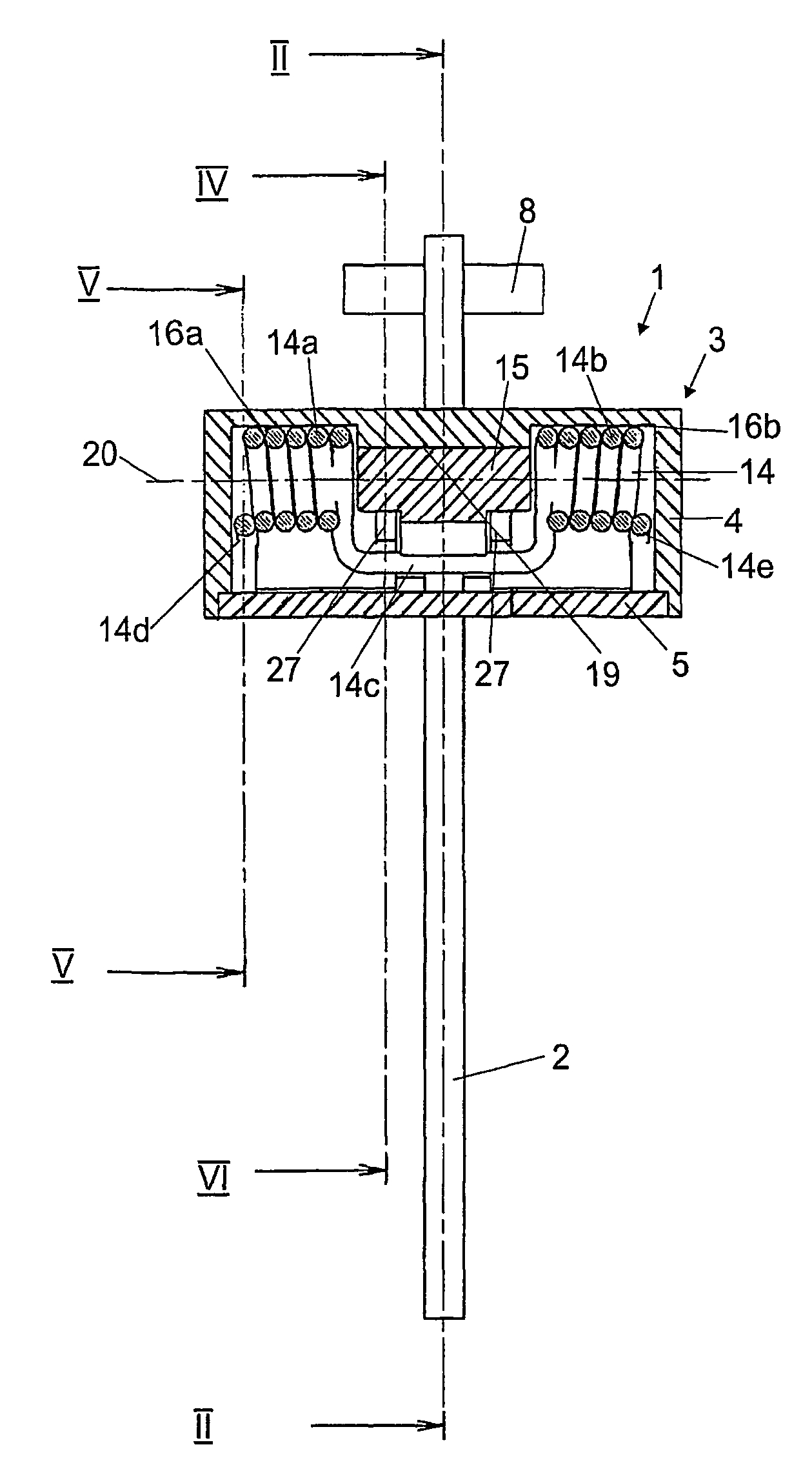
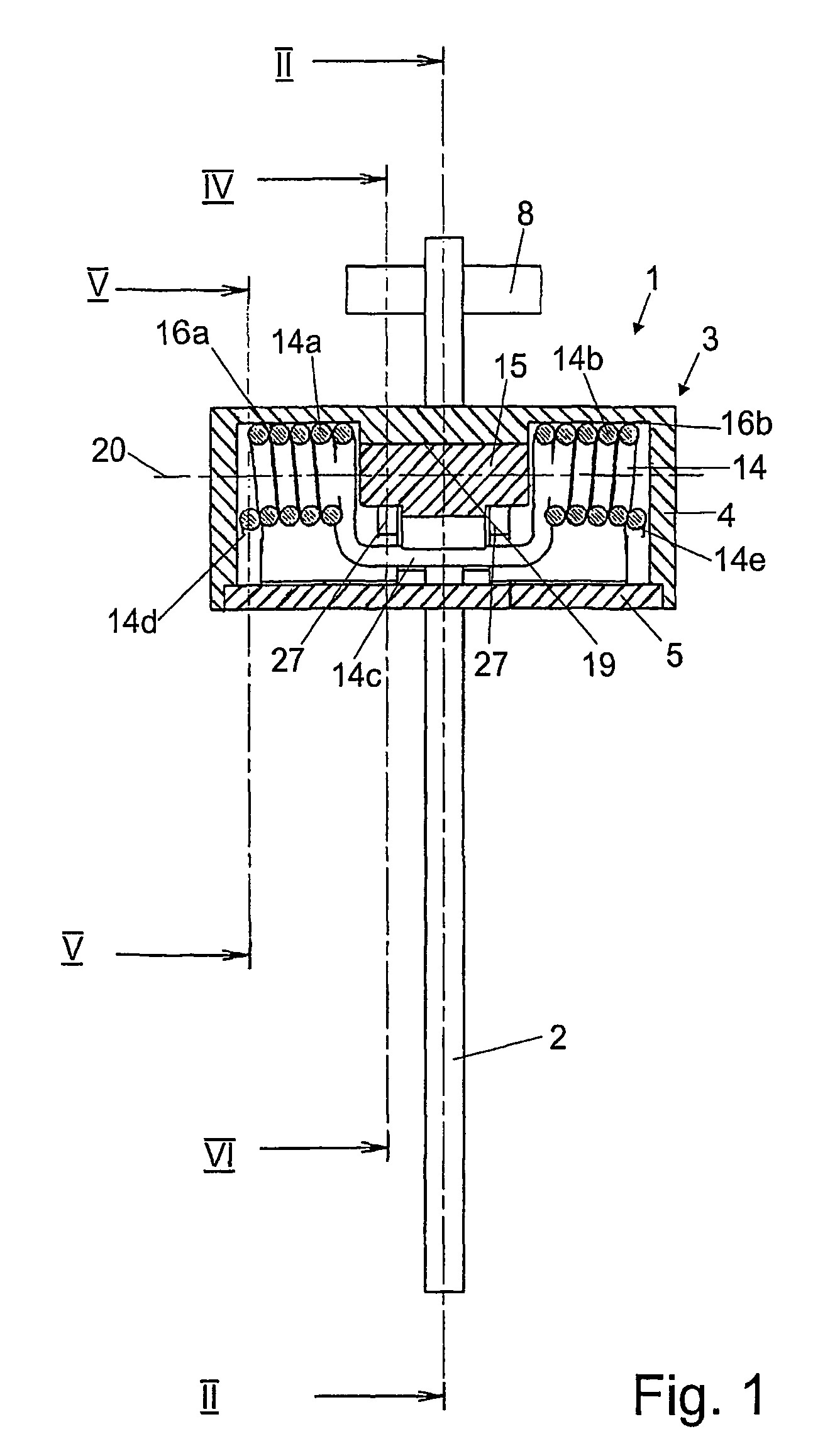
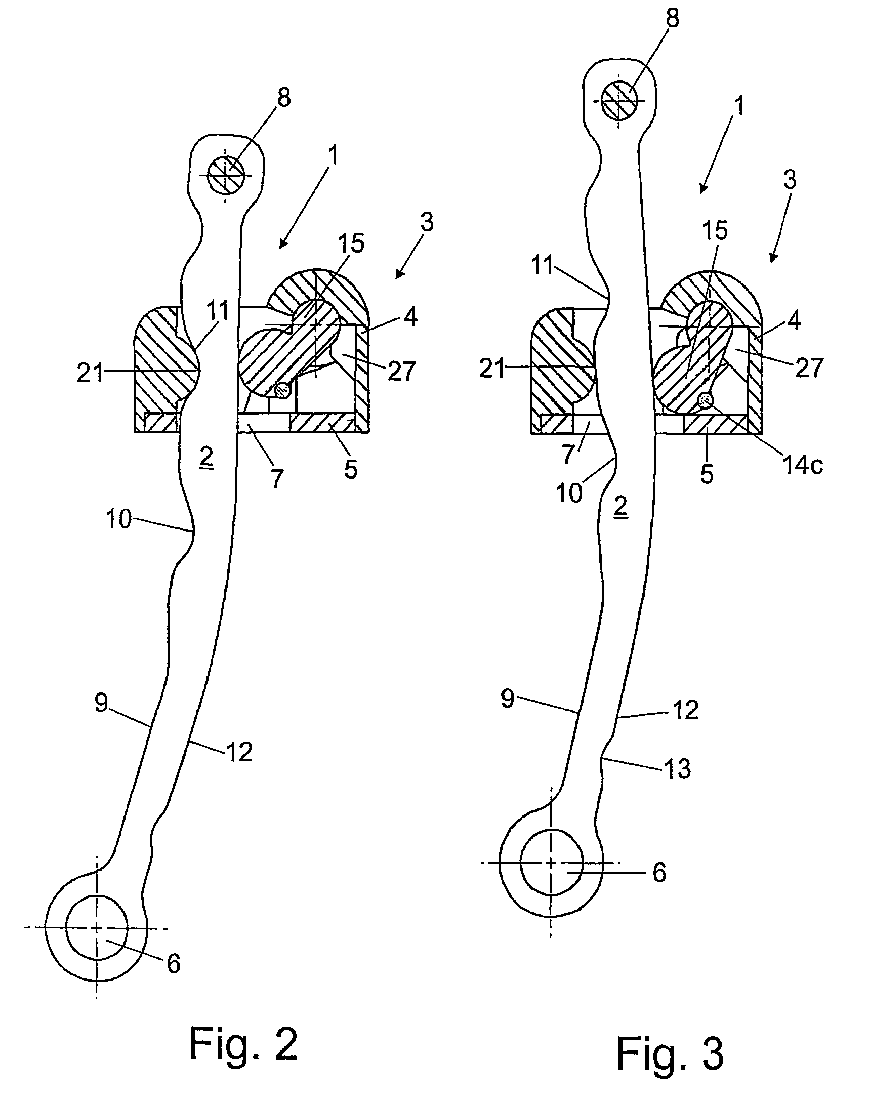
[0063]The door arrester illustrated in FIGS. 1 to 6, which is referred to overall by reference number 1, comprises a retaining bar 2 and a housing 3, which is composed of a first housing part 4 and a second housing part 5 which both consist of plastic and are clipped to each other.

[0064]The retaining bar 2 has, at its one end, a bearing eyelet 6 for fastening it pivotably to a door assembly part, for example to a door of a motor vehicle, and is guided through an opening 7 of the housing 3, a stop 8, which passes through the other end of the retaining bar 2, preventing the retaining bar 2 from tearing out of the housing 3 and restricting the pivoting path of the door. The retaining bar 2 is designed, for example, as a metallic blank of flat material which can be produced by stamping or forging, it being possible for this purpose also for a plurality of blanks of flat material, for example two, to be placed on one another and to be connected to one another in the region of the bearing...


PUM


Abstract

A door arrester for a door of a motor vehicle includes a holder housing including a passage opening for a retaining bar, the holder housing including a first supporting housing part. The first supporting housing part includes injection-molded plastic and a fastening portion for fixing the holder housing onto a part of the motor vehicle. A swinging element and a spring element are provided. The swinging element is pivotable relative to the passage opening toward the retaining bar. The spring element acts upon the swinging element. The first housing part includes a bearing for receiving the swinging element.

Description

[0001]The invention relates generally to door arresters, and in particular to a door arrester for motor vehicle doors, comprising a holder housing with a passage opening for a retaining bar, a swinging element which can be pivoted relative to the passage opening in the direction of the narrow side of the retaining bar, and a spring element for acting upon the swinging element.BACKGROUND[0002]DE 41 23 775 A1 describes a door arrester, in which a door-retaining rod, which is provided with latching markings, is fastened pivotably with its one end to one of the door assembly parts comprising the door and door pillar and can be passed with its other end into a metal holder housing which can be fixed to the corresponding, other door assembly part. In this case, an abutment roll is arranged rotatably in the holder housing on one side of the retaining bar, said abutment roll being in contact with a surface of the retaining bar that is formed without latching markings, and on the other side ...

Claims


Application Information

Patent Timeline
IPC IPC(8): E05C17/18E05B15/16E05B17/00E05C17/20
CPCE05B17/0045E05C17/203E05B17/0041E05B2015/1664Y10T16/61E05B77/42Y10T292/305Y10T292/288
Inventor SCHMOLL, THOMASPLASBERG, GUNTERHOFFMANN, PETERHEINRICHS, GUNDOLFDUNING, RALF
Owner EDSCHA ENG GMBH
Why Eureka
Try Eureka