Image forming apparatus

Inactive Publication Date: 2009-06-30
FUNAI ELECTRIC CO LTD
View PDF17 Cites 13 Cited by
  • Summary
  • Abstract
  • Description
  • Claims
  • Application Information

AI Technical Summary

Benefits of technology

[0008]An object of the present invention is to provide an image forming apparatus comprising an openable and closable paper feed tray that can keep the paper feed tray properly attached to the apparatus body even when a user grasps the paper feed tray to lift up the apparatus.
[0009]Another object of the present invention is to provide an image forming apparatus that comprises an openable and closable paper feed tray and a cover tray doubling as a manual feed tray, wherein the cover tray does not obstruct opening and closing of the paper feed tray and the cover tray can be easily set for manual feed printing.
[0016]When a downward force is applied to the cover tray in the position where the second protrusions are placed on the first protrusions with the connection portions connected to the second pivot shafts at the apparatus body, the second protrusions are pressed into the space between the first protrusions so as to move to the position below the first protrusions, making use of bending of the paper feed tray and the cover tray. Accordingly, by applying a downward force to the cover tray, a user can easily change the position of the cover tray from the position for use as the manual feed tray to the position for use as the cover.
[0019]With this configuration, each of the second protrusions has the first inclined surface formed so that its height from the corresponding second side wall increases from the lower end to the upper end, so that when the second protrusions are pressed downward into the space between the first protrusions, they gradually move along the first inclined surfaces. Accordingly, the second protrusions can be smoothly moved downward from the position above the first protrusions.
[0020]Further, each of the second protrusions has the second inclined surface formed so that its height from the corresponding second side wall increases from the upper end to the lower end, so that when the second protrusions are pressed upward into the space between the first protrusions, they gradually move along the second inclined surfaces. Accordingly, the second protrusions can be smoothly moved upward from the position below the first protrusions.
[0022]With the above configuration, when the force acts on the paper feed tray in the closed position to bend inward the first side walls of the paper feed tray, the first protrusions of the paper feed tray come in contact with the portions of the paper pressing plate where the notches are formed, so that the inward bending of the first side walls can be stopped. This can prevent the supported portions formed on the outer surfaces of the first side walls from being displaced by a large amount from their normal positions, thus preventing the paper feed tray from becoming detached from the apparatus body.

Problems solved by technology

However, there is no known image forming apparatus that comprises an openable and closable paper feed tray and a cover tray doubling as a manual feed tray, wherein the cover tray does not obstruct opening and closing of the paper feed tray and the cover tray can be easily set for manual feed printing.

Method used


Image

  • Image forming apparatus
  • Image forming apparatus
  • Image forming apparatus

Examples


Embodiment Construction

[0040]Referring now to the accompanying drawings, a preferred embodiment of the present invention is described. It is to be noted that the following description of preferred embodiment of the present invention has been presented for purposes of illustration and description, and is not intended to be exhaustive or to limit the present invention to the precise form disclosed.

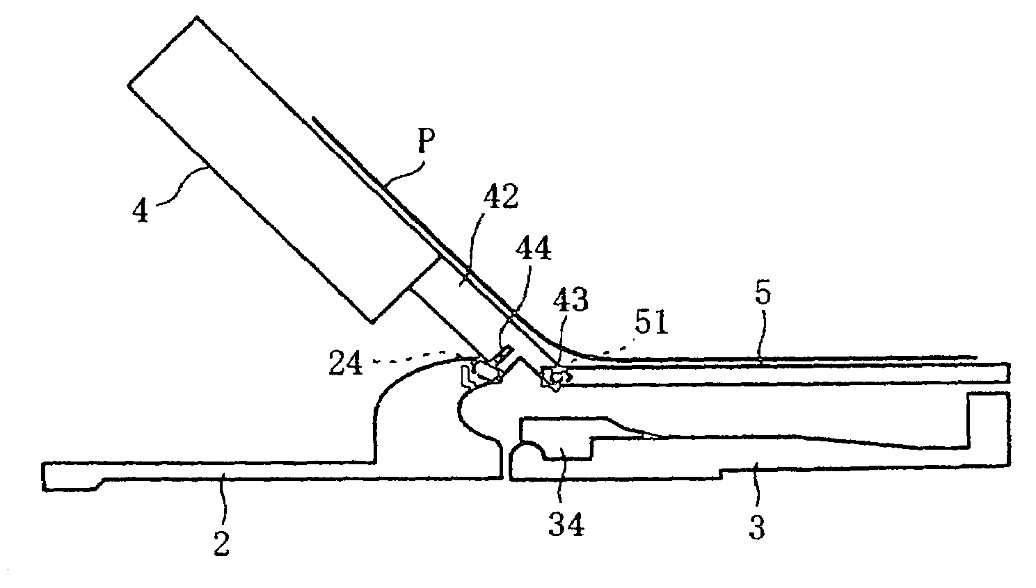
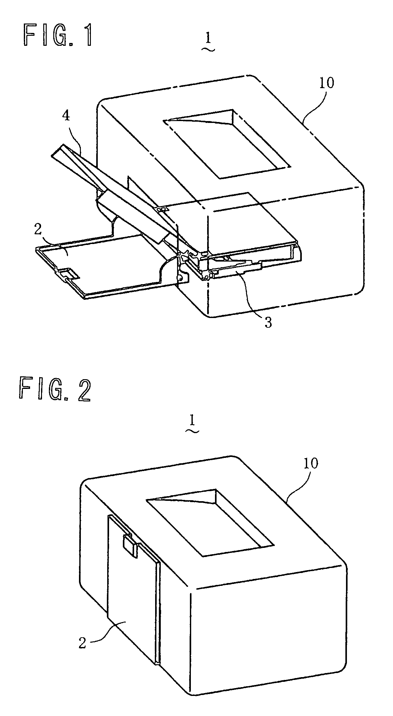
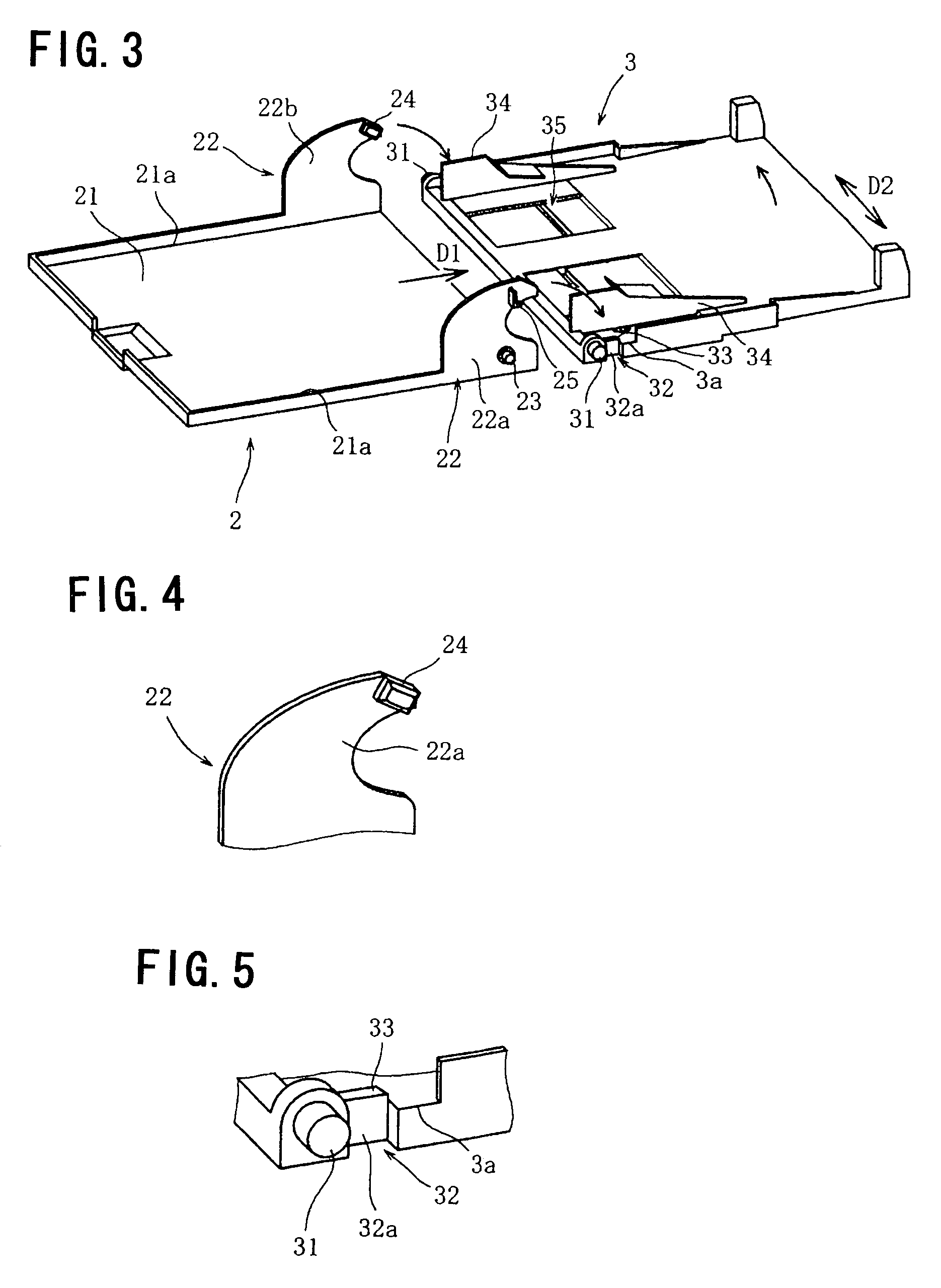
[0041]FIG. 1 shows a printer 1 according to one embodiment of the present invention. The printer 1 is an apparatus that prints an image on a sheet of paper or the like based on image data (which may contain text data) input via a device such as a personal computer connected thereto. As shown in FIG. 1, the printer 1 comprises a paper feed tray 2 that is attached to the printer body 10 so as to be freely opened and closed with respect to the printer body 10 and that, in use, is opened to a substantially horizontal position for holding a stack of paper thereon; a paper pressing plate 3 that presses a paper sheet pla...


PUM


Abstract

An image forming apparatus comprises a paper feed tray that can be opened and closed with respect to the apparatus body and a cover tray that can double as a manual feed tray. The paper feed tray has first side walls and first protrusions formed on the inner surfaces of the first side walls. The cover tray has: connection portions that are configured to be detachably connected to pivot shafts provided at the apparatus body and that are connected to the pivot shafts so as to rotate about the pivot shafts; second side walls; and second protrusions formed on the outer surfaces of the second side walls. The cover tray serves as a cover for covering sheets of paper stacked on the paper feed tray when it is in a position where the second protrusions are located below the first protrusions. The cover tray serves as a manual feed tray when it is in a position where the second protrusions are placed on the first protrusions so that the cover tray is inclined with one end adjacent to the pivot shafts located lower than the other end.

Description

BACKGROUND OF THE INVENTION[0001]1. Field of the Invention[0002]The present invention relates to image forming apparatus such as printers, copiers, facsimiles, and the like.[0003]2. Description of the Related Art[0004]There are known image forming apparatus such as printers comprising a paper feed tray that is attached to the apparatus body so as to be freely opened and closed with respect to the apparatus body and that, in use, is opened to a horizontal position for holding a stack of paper thereon (see, for example, Japanese laid-open patent publication Nos. 2002-347997, Hei 7-309454, Hei 8-198480, and 2003-118854). Such an apparatus is designed so that the paper feed tray is kept closed when the apparatus is not in use, and it is opened for holding paper sheets when the apparatus is used, thereby saving space.[0005]Image forming apparatus are also known that comprise a cover tray to be set for covering paper sheets stacked on a paper feed tray so as to prevent dust and dirt from ...

Claims


Application Information

Patent Timeline
Patent Type & Authority Patents(United States)
IPC IPC(8): B41J11/58
CPCB41J13/103B41J29/13
Inventor BANDOU, TAKAYOSHIIMURA, YOSHIHIKO
Owner FUNAI ELECTRIC CO LTD
Why Eureka
Try Eureka