Supercharge Your Innovation With Domain-Expert AI Agents!

Slide lock panel-mount connector

a technology of sliding lock and connector, which is applied in the direction of coupling device connection, substation/switching arrangement details, coupling protective earth/shielding arrangement, etc., can solve the problems of difficult tightening and untightening of thumb screws, restricted removal of receptacle connectors from plug connectors, and use of such known thumb screws

Inactive Publication Date: 2009-06-30
TE CONNECTIVITY CORP
View PDF12 Cites 10 Cited by
  • Summary
  • Abstract
  • Description
  • Claims
  • Application Information

AI Technical Summary

Benefits of technology

This solution enables convenient and efficient mating and mounting of electrical connectors, reducing stress on contacts and eliminating the need for tools, thereby simplifying assembly and enhancing system reliability.

Problems solved by technology

By tightening the thumb screws, the connectors become fully mated, and removal of the receptacle connector from the plug connector is restricted.
However, other problems are associated with the use of such known thumb screws.
Particularly, tightening and un-tightening the thumb screws is difficult and sometimes uncomfortable for the user.
Additionally, tightening and un-tightening the thumb screws is time consuming.
Some known connectors suffer from problems associated with the mating of the connectors.
Sometimes visibility or accessibility are limited, which makes it difficult for a user to align and orient the connectors.
As a result, the connectors are more difficult to mate with one another because the mating force required to fully mate the connectors is increased.
Improper mating of the connectors may lead to a partial or complete failure of the system operated by the connectors.
Moreover, the plug connectors are typically mounted to a panel or chassis, and the accessibility of the panel may be limited.
As such, it may be difficult to properly mount the plug connector during assembly.
However, multiple components and / or other plug connectors may be attached to the panel or may be positioned in the vicinity of the panel, making it difficult to access the panel to tighten the screws to attach the plug connector to the panel.
As such, the assembly of the plug connector with the panel may be difficult and time consuming.

Method used


Image

  • Slide lock panel-mount connector
  • Slide lock panel-mount connector
  • Slide lock panel-mount connector

Examples


Embodiment Construction

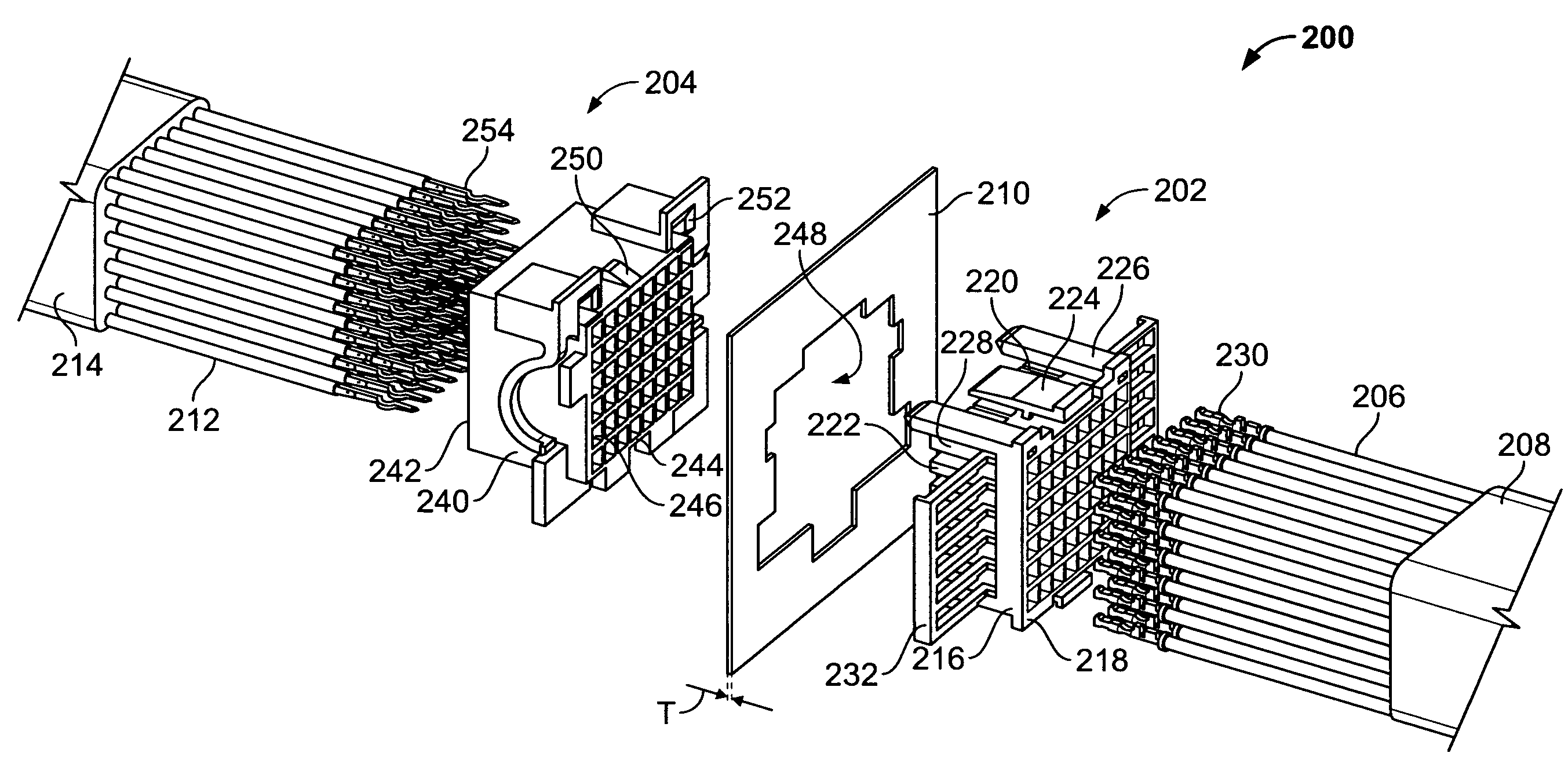
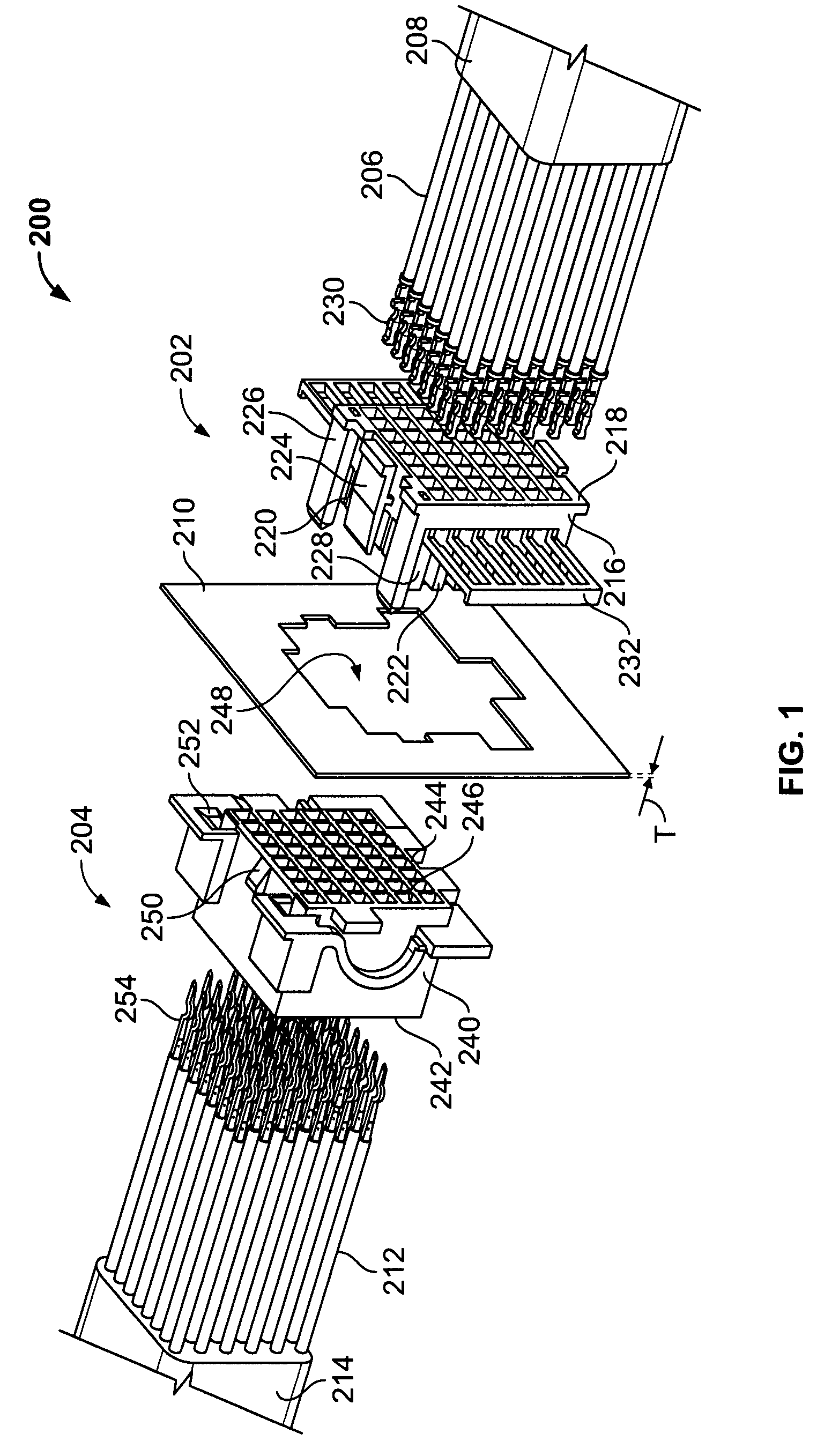
[0016]FIG. 1 is an exploded perspective view of a connector assembly 200 having a receptacle connector 202 and a plug connector 204. In the illustrated embodiment, the receptacle connector 202 is a cable connector for terminating a plurality of wires 206 of a cable 208. The cable 208 may be transmitting power, data, or both. In the illustrated embodiment, the plug connector 204 is a panel connector that may be mounted to a panel, a backplane, a chassis or the like, generally identified 210. The panel 210 generally has opposed planar surfaces separated by a thickness T. Optionally, the plug connector 204 may be terminated to wires 212 of another cable 214. As such, the connector assembly 200 generally defines a cable-to-cable connector assembly. Alternatively, the plug connector 204 may be terminated to an integrated circuit or circuit board (not shown).

[0017]The receptacle connector 202 may be similar to the receptacle connector as described in commonly owned U.S. application Ser. N...


PUM


Abstract

An electrical connector for mounting to a panel includes a housing configured to be mounted to the panel, and a deflectable latch including a latch arm having a length extending in a longitudinal direction between a fixed end secured to the housing and a free end movable with respect to the housing. The free end has a locking finger extending therefrom. The latch arm is deflected laterally with respect to the length thereof to align the locking finger with an opening through the panel. The deflectable latch returns to a resting position once the housing is mounted to the panel, and the locking finger engages the panel when in the resting position.

Description

BACKGROUND OF THE INVENTION[0001]This invention relates generally to electrical connectors, and more specifically, to slide lock panel-mount connectors.[0002]Conventional cable-to-cable or cable-to-board connectors typically include a receptacle connector and a plug connector. Contacts of the connectors are interconnected to one another during mating of the connectors. At least some known connectors provide thumb screws on the receptacle connector that may be secured to the plug connector or chassis surrounding the plug connector. By tightening the thumb screws, the connectors become fully mated, and removal of the receptacle connector from the plug connector is restricted. However, other problems are associated with the use of such known thumb screws. Particularly, tightening and un-tightening the thumb screws is difficult and sometimes uncomfortable for the user. Additionally, tightening and un-tightening the thumb screws is time consuming.[0003]Some known connectors suffer from p...

Claims


Application Information

Patent Timeline
Patent Type & Authority Patents(United States)
IPC IPC(8): H01R13/648
CPCH01R13/743
Inventor WHITEMAN, JR., ROBERT NEILRITTER, CHRISTOPHER DAVID
Owner TE CONNECTIVITY CORP
Features
  • R&D
  • Intellectual Property
  • Life Sciences
  • Materials
  • Tech Scout
  • Unparalleled Data Quality
  • Higher Quality Content
  • 60% Fewer Hallucinations
Learn More