UWB (Ultra Wide Band) waveform design to minimize narrowband interference

Inactive Publication Date: 2009-06-30
AVAGO TECH WIRELESS IP SINGAPORE PTE
View PDF6 Cites 15 Cited by
  • Summary
  • Abstract
  • Description
  • Claims
  • Application Information

AI Technical Summary

Benefits of technology

[0021]Alternatively, the positions of the devices within the piconet may be performed using GPS (Global Positioning System) functionality contained within the devices. For example, the PNC may include GPS functionality that is operable to determine the specific location of the PNC within a degree of precision, and each DEV of the plurality of DEVs includes GPS functionality that is operable to dete

Problems solved by technology

However, other piconets may be implemented such that the devices do not operate according to such an M / S (Master / Slave) type relationship.
However, within a scatternet implementation, a problem may arise such that each of the individual piconets must be able to operate in relative close proximity with other piconets without interfering with one another.
This inherently requires a great deal of synchronization between the piconets, which may be very difficult to achieve in some instances.
It is also noted that independently operating piconets, not implemented within a scatternet implementation, may also suffer from deleterious effects of interference with other piconets located within relative close proximity.
As piconets are currently being developed in conjunction with many of the other wireless communication systems (e.g., the various IEEE 802.11 communication systems—including IEEE 802.11a and IEEE 802.11b WLANs (Wireless Local Area Networks)), there is a possibility that the various wireless communication systems may interfere with one another.
When a piconet operates in relatively close proximity to these types of communication system (or other wireless communication systems) there is a relatively high possibility that the piconet may experience interference when employing signals operating around these frequency ranges.

Method used


Image

  • UWB (Ultra Wide Band) waveform design to minimize narrowband interference
  • UWB (Ultra Wide Band) waveform design to minimize narrowband interference
  • UWB (Ultra Wide Band) waveform design to minimize narrowband interference

Examples


Embodiment Construction

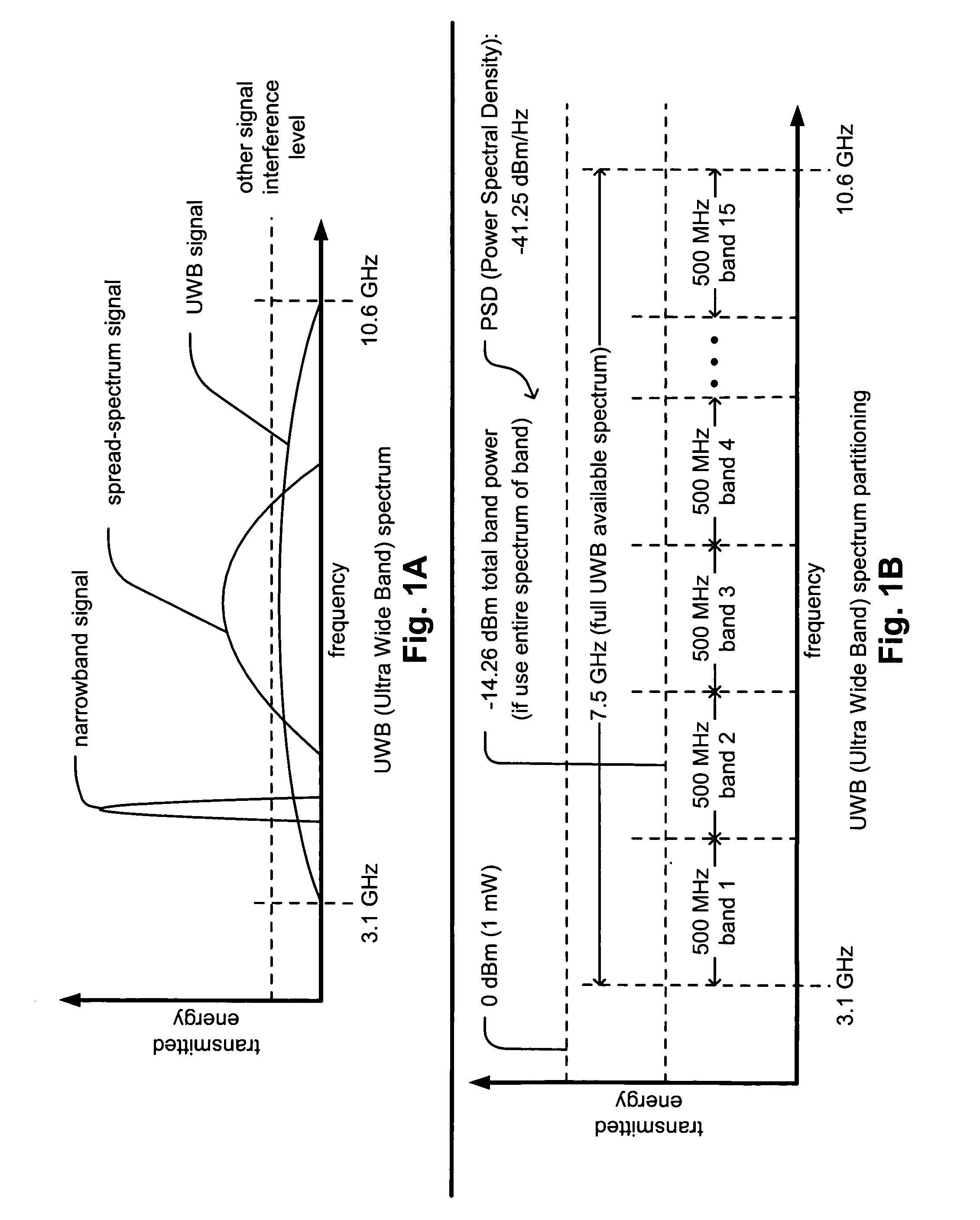
[0046]FIG. 1A is a diagram illustrating an embodiment of the frequency spectrum of a UWB (Ultra Wide Band) signal when compared to some other signal types according to the invention. In contradistinction to RF (Radio Frequency) communications that operate by using a narrowband frequency carrier to transmit information, UWB communications operate by sending pulses of energy across a broad frequency spectrum. For example, an RF signal may be viewed as occupying the range of spectra of a narrowband frequency. Also, in contradistinction to a spread-spectrum signal whose PSD (Power Spectral Density) generally rises above the PSDs of other interfering signals within an available spectrum and also occupies a relatively narrower portion of the available spectrum, a UWB signal may actually be viewed as being a pulse shaped signal (that may never exceed the PSDs of other interfering signals within the available spectrum). A spread-spectrum signal may be viewed a signal that occupies a frequen...


PUM


Abstract

UWB (Ultra Wide Band) waveform design to minimize narrowband interference. A novel solution is presented such that a PN (Pseudo-Noise) code may be intelligently designed so as to null portions of a UWB spectrum that have a significant amount of noise. These narrowband blocking intervals will effectively block off all of the interference within these portions of the UWB signal. These spectrum portions having interference may be predetermined beforehand or determined by one or more of the devices within the communication system; in addition, any changes in the interference may also be assessed in real time or successively (e.g., after the elapse of every predetermined period of time). Moreover, the position of the devices within the communication system may also be employed when selecting the nulling codes, and they may be adaptively changed, in real time, to respond to changes in the interference and / or changes in the devices' positions.

Description

CROSS REFERENCE TO RELATED PATENTS / PATENT APPLICATIONS[0001]The present U.S. Utility Patent Application claims priority pursuant to 35 U.S.C. §119(e) to the following U.S. Provisional Patent Applications which are hereby incorporated herein by reference in their entirety and made part of the present U.S. Utility Patent Application for all purposes:[0002]1. U.S. Provisional Application Ser. No. 60 / 472,336, entitled “Position based WPAN (Wireless Personal Area Network) management,” filed May 21, 2003 (May 21, 2003), pending.[0003]2. U.S. Provisional Application Ser. No. 60 / 473,776, entitled “UWB (Ultra Wide Band) waveform design to minimize narrowband interference,” filed May 28, 2003 (May 28, 2003), pending.[0004]The following U.S. Utility Patent Application, being filed concurrently, is hereby incorporated herein by reference in its entirety and made part of the present U.S. Utility Patent Application for all purposes:[0005]1. U.S. Utility Patent Application Ser. No. 10 / 668,527, ent...

Claims


Application Information

Patent Timeline
IPC IPC(8): H04B7/216H04B1/69H04L1/20H04L12/28H04L12/56
CPCH04B1/719H04J13/0022H04L1/20H04W84/12H04B1/71635H04W64/00
Inventor KARAOGUZ, JEYHAN
Owner AVAGO TECH WIRELESS IP SINGAPORE PTE
Why Eureka
Try Eureka