Gas combustion type driving tool

a driving tool and gas combustion technology, applied in the direction of manufacturing tools, nailing tools, stapling tools, etc., can solve the problems of fastener instability, fastener instability in attitude when driven, and inability to positively drive the fastener in its proper attitude, etc., to achieve high pressure

Active Publication Date: 2009-07-07
MAX CO LTD
View PDF14 Cites 15 Cited by
  • Summary
  • Abstract
  • Description
  • Claims
  • Application Information

AI Technical Summary

Benefits of technology

[0009]One or more embodiments of the invention provides a gas combustion type driving tool which not only can supply sufficiently high pressure to a feed piston / cylinder device functioning as a fastener feed device but also can delay the retreat operation of a feed piston included in the feed piston / cylinder device.
[0013]According to one or more embodiments of the invention, in the gas combustion type driving tool, there is interposed a gas conduit between the combustion chamber and feed piston / cylinder device and, in the gas conduit, there is disposed the operation delay device for actuating the feed piston of the feed piston / cylinder device against the above-mentioned spring in such a manner that such actuation is delayed with respect to the operation of the striking piston caused by the combustion of the mixed gas within the combustion chamber. Owing to this, with the combustion of the mixed gas within the combustion chamber, the striking piston is operated for striking and the feed piston is operated for retreating in such a manner that the operation of the feed piston is delayed with respect to the striking operation of the striking piston: that is, until the leading nail within the nose part is struck by the driver and driven out from the nose part by the striking operation of the striking piston, the feed piston is not operated for retreating. Therefore, when the leading nail is driven out from the nose part, it is pressed against the inner surface of the nose part and is thus stable in attitude. Thus, the leading nail can be driven out properly.
[0014]Also, since the pressure of the combustion gas combusted within the combustion chamber (in the upper portion of the striking piston) is fed from the gas conduit to the feed piston / cylinder device, a sufficiently high pressure can be supplied to the feed piston / cylinder device. Further, in a structure where, in the intermediate portion of the gas conduit, there is disposed a delay cylinder having one end opened to the combustion chamber with the other end opened to the feed cylinder and, when a delay piston slidable within the delay cylinder due to the pressure of the combustion gas is slid from the above-mentioned one end of the delay cylinder to the other end thereof, air compressed within the delay cylinder is supplied from the other end of the other end of the delay cylinder to the feed cylinder, the supply of the gas pressure on the combustion chamber side can be delayed by the time necessary for the pressure of the air, which is compressed when the delay piston slides from one end to the other end of the delay cylinder, to rise so sufficiently as to be able to retreat the feed piston.
[0016]And, in a structure where, in the intermediate portion of the gas conduit, there is disposed a timing valve device including a valve member which, when the valve member is present in one end of the timing valve device, closes the gas conduit connecting together the combustion chamber and feed cylinder and, when the valve member is moved to the other end of the timing valve device due to the pressure of the combustion gas, opens the gas conduit, even when the mixed gas is burned within the combustion chamber, during the time while the valve member is moving from its top dead center position to the gas conduit opening position, the gas conduit remains closed and thus the pressure of the combustion gas is not supplied to the delay cylinder. Therefore, according to this structure, the retreat operation of the feed piston can be delayed by the time sufficient to retreat the feed piston.

Problems solved by technology

However, in a structure where a combustion chamber and a feed cylinder are directly connected to each other, as shown in FIG. 13, the combustion gas is applied to both of the striking piston and feed piston (feed claw) substantially at the same time; therefore, almost simultaneously with the striking operation of the striking piston, the feed piston is also retreated, thereby causing the fasters to be unstable in attitude when they are driven.
However, when a striking device is actuated due to the pressure of the combustion gas and thus the driver is driven together with a striking piston whereby the faster is driven and the piston is retreated simultaneously, a force for pressing and holding the fastener is lost to thereby cause the faster to be unstable in attitude, which makes it impossible to positively drive the fastener in its proper attitude.
However, at the position slightly lower than the top dead center of the striking piston, the pressure of the combustion gas is reduced slightly, which in turn reduces the pressure to be applied to the feed cylinder of the feed device.
This makes it necessary to increase the quantity of gas to be supplied into the feed cylinder, which also results in the increased size of the feed device.

Method used


Image

  • Gas combustion type driving tool
  • Gas combustion type driving tool
  • Gas combustion type driving tool

Examples


Embodiment Construction

[0041]Now, description will be given below of exemplary embodiments according to the invention with reference to the accompanying drawings.

[0042]Here, a driving tool according to the invention is not limited to a nail driving tool. That is, the invention can be applied to a driving tool which feeds connected fasteners such as headed bar members (nails or screws) and headless bar members (parallel pins) while transmitting power using the combustion of a mixed gas.

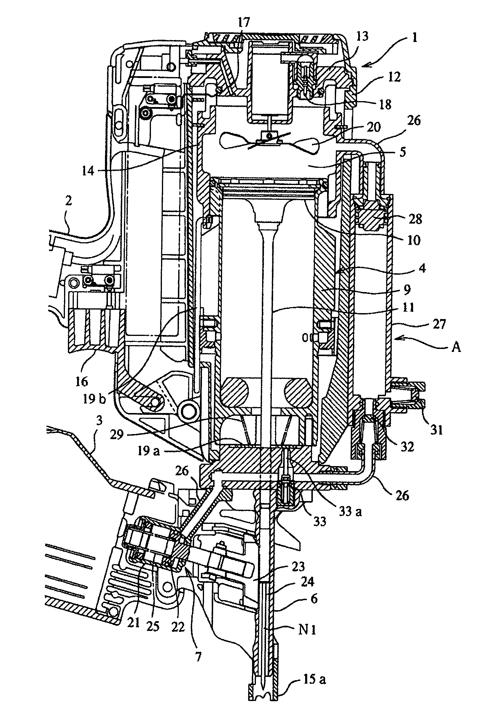
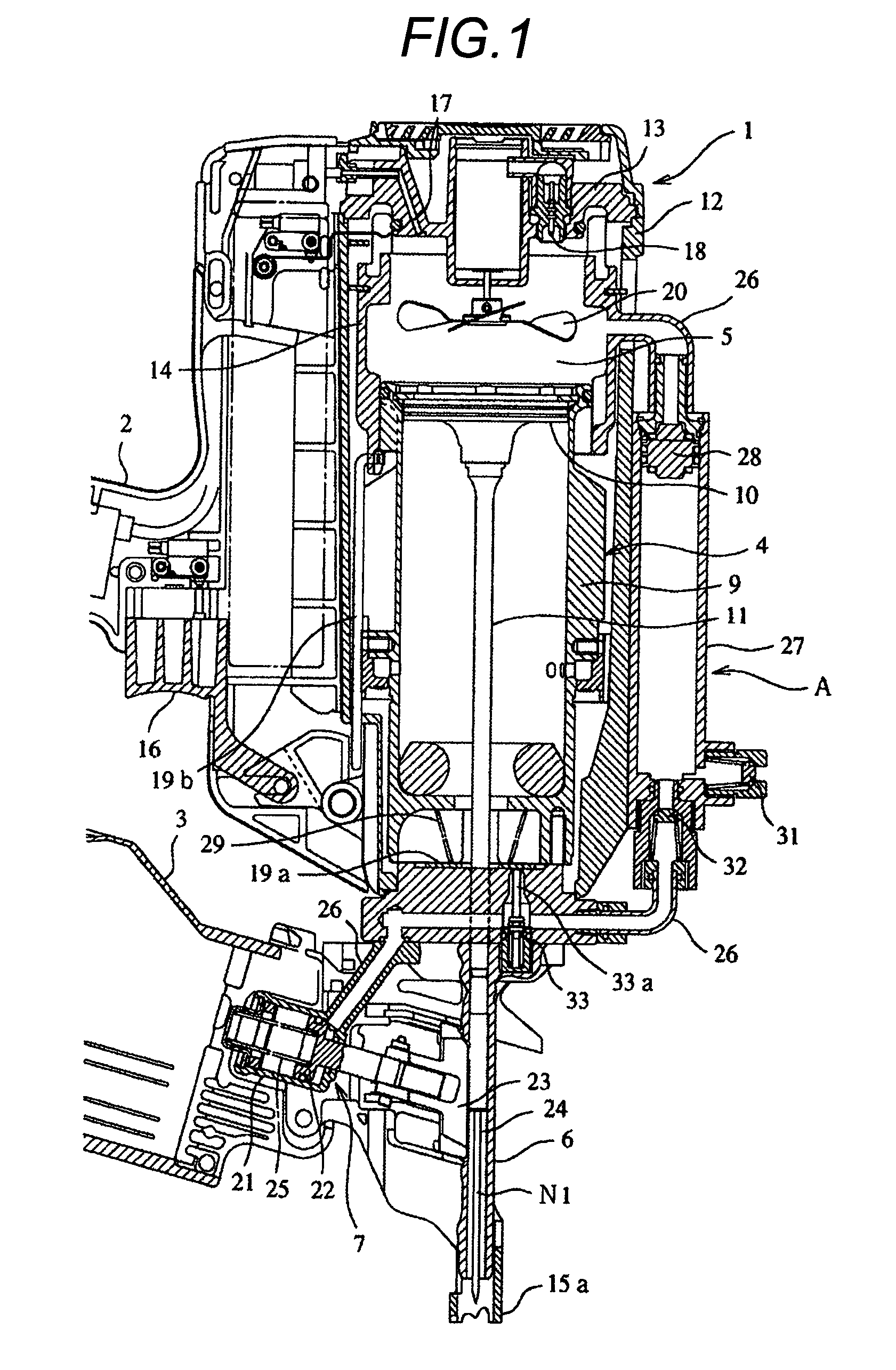
[0043]In FIG. 1, reference numeral 1 designates the body of a gas combustion type nail driving tool. To the body 1, there are connected a grip 2 and a magazine 3; and, on the body 1, there are provided a striking piston / cylinder device 4, a combustion chamber 5, a nose part 6, and a feed piston / cylinder device 7 for nail feeding.

[0044]The striking piston / cylinder device 4 is structured such that a striking piston 10 is slidably accommodated within a striking cylinder 9 and a driver 11 is connected to the lower portion of the...


PUM


Abstract

In a gas combustion type driving tool, on a feed cylinder 21 included in a feed piston / cylinder device 7, there is provided a spring for normally urging a feed piston 22 in a feed direction. A portion of the feed cylinder 21 opposite to the spring is connected to a combustion chamber 5 through a gas conduit 26. In an intermediate portion of the gas conduit 26, there is provided a delay piston / cylinder device A. One end of a delay cylinder 27 is disposed on the combustion chamber 5 side, while the other end thereof is disposed on the feed cylinder 21 side. When a delay piston 28 is slidingly moved from one end of the delay cylinder 27 to the other end thereof by the pressure of combustion gas, air compressed within the delay cylinder 27 is supplied from the other end of the delay cylinder 27 to the feed cylinder 21.

Description

TECHNICAL FIELD[0001]The present invention relates to a gas combustion type driving tool which comprises: a combustion chamber for explosively combusting a mixture gas produced by stirring and mixing together combustible gas and air; a drive piston / cylinder device which is driven by a combustion gas; a nose part for slidingly guiding a driver connected to the drive piston to thereby drive out a fastener therefrom; a feed piston / cylinder device for feeding the fastener to the nose part; and an operation delay device for delaying a retreat operation of a feed claw included in the feed piston / cylinder device.BACKGROUND ART[0002]As an example of a gas combustion type driving tool, there is known a combustion gas drive type driving tool in which combustible gas is charged into a combustion chamber formed in a hermetically closed manner within a tool body to stir up a mixed gas composed of combustible gas and air within the combustion chamber, a stirred mixed gas is combusted within the c...

Claims


Application Information

Patent Timeline
Patent Type & Authority Patents(United States)
IPC IPC(8): B27F7/09
CPCB25C1/08B25C1/00B27F7/09
Inventor MURAYAMA, KATSUHIKOTAKEMURA, HAJIMETAMURA, JUNICHI
Owner MAX CO LTD
Why Eureka
Try Eureka