Redundant time synchronization

a time synchronization and redundancy technology, applied in multiplex communication, instruments, generating/distributing signals, etc., can solve problems such as system vulnerability to falling out of synchronization and time synchronization problems, and achieve the effect of avoiding collisions

Active Publication Date: 2009-07-07
SCHNEIDER ELECTRIC SYST USA INC
View PDF3 Cites 5 Cited by
  • Summary
  • Abstract
  • Description
  • Claims
  • Application Information

AI Technical Summary

Problems solved by technology

Problems with time synchronization can arise especially when different systems are integrated or operated together and must operate on a common clock.
Although it is possible to simply transmit a clock signal from one system to another, this technique leaves the system vulnerable to falling out of synchronization due to a disruption of the line carrying the clock signal or the machine supplying the signal.

Method used


Image

  • Redundant time synchronization
  • Redundant time synchronization
  • Redundant time synchronization

Examples


Embodiment Construction

[0019]Turning to the drawings, wherein like reference numerals refer to like elements, the present invention is illustrated as being implemented in a suitable environment. The following description is based on embodiments of the invention and should not be taken as limiting the invention with regard to alternative embodiments that are not explicitly described herein.

[0020]In embodiments of the invention, a time-synchronization algorithm is provided for clock synchronization between two disparate systems, such as between a controller system and a system having one or more application workstations. Although the illustrated examples pertain primarily to integration of the Triconex controller system with a workstation system such as the Foxboro I / A system, it will be appreciated that the time-synchronization method and system described herein are also applicable to other environments.

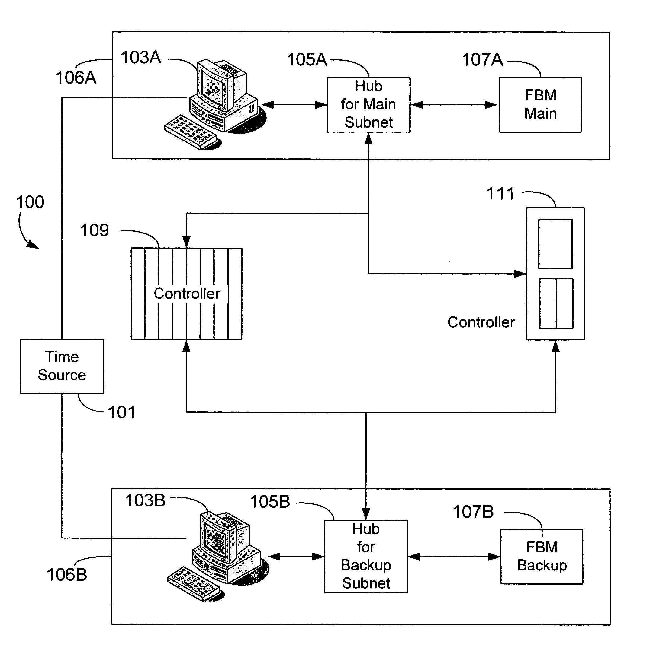
[0021]FIG. 1 is a schematic illustration of a redundant, time-synchronization system employed between an...


PUM


Abstract

Disclosed is a time-synchronization algorithm for use among disparate systems, such as between a controller system and a system having one or more application workstations. In an embodiment of the invention, the workstation system acts as a master timekeeper, ensuring that the time stored in the controller system is in synchrony with the time kept by the workstation system. In a further embodiment of the invention, the time-synchronization system provides staggered time-synchronization signals from each of two or more workstations for receipt by the controller system. The controller system sets its local time by resetting the time for each such incoming synchronization signal. In a further embodiment of the invention, each of two or more workstations employs a technique for evaluating the error accumulated in the controller's time clock and transmits a time-synchronization message in response to finding that the accumulated error has exceeded a predetermined acceptable error threshold.

Description

CROSS-REFERENCE TO RELATED APPLICATION[0001]This application claims priority to U.S. Provisional Patent Application 60 / 709,580, “Triconix Redundant Time Synchronization,” which was filed on Aug. 19, 2005, and which is incorporated herein by reference in its entirety.FIELD OF THE INVENTION[0002]The present invention is related generally to coordination among multiple systems, and, more particularly, to time synchronization among multiple systems.BACKGROUND OF THE INVENTION[0003]Many industrial and other processes rely on accurate timing of processes and data flow. For example, steps may need to be taken in a certain sequence or with certain timing, and accurate clock information is critical in such situations. Problems with time synchronization can arise especially when different systems are integrated or operated together and must operate on a common clock. Although it is possible to simply transmit a clock signal from one system to another, this technique leaves the system vulnerab...

Claims


Application Information

Patent Timeline
Patent Type & Authority Patents(United States)
IPC IPC(8): H04J3/06H04B7/005H04L7/00
CPCG06F1/12H04J3/0667G06F1/14
Inventor GUNSTON, KENNETH ARTHURMENDU, KRISHNA RAO
Owner SCHNEIDER ELECTRIC SYST USA INC
Why Eureka
Try Eureka