Cooperative control system of robots

a robot and cooperative technology, applied in the field of cooperative control systems of robots, can solve the problems of inability to maintain the plurality of control units, inability to poll for the flag or stand inability to use the waiting time such as polling for the flag or standing by for an event, so as to prevent the variation of the relative position and posture of the master and slave robots, and achieve the effect of high precision and relative position and posture relationship

Active Publication Date: 2009-07-07
KAWASAKI HEAVY IND LTD
View PDF26 Cites 23 Cited by
  • Summary
  • Abstract
  • Description
  • Claims
  • Application Information

AI Technical Summary

Benefits of technology

[0021]The control unit set to the slave function execution mode changes the minimum interruption period so as to make the communication delay time (tb−ta) from the time ta when the control unit set to the master function execution mode transmits the operation instruction to the time tb when the control unit set to the slave function execution mode receives the operation instruction and starts controlling its own robot equal to the predetermined time T. As a result, the time tb when the slave side control unit starts controlling its own robot is prevented from greatly varying from the time ta when the master side control unit transmits the operation signal to the master side control unit so as to become longer or shorter than the predetermined time T. By doing this, the time variation for the operation of the slave robot from the master robot is restricted, thus the robots can be cooperatively operated precisely.
[0039]In the relative position relationship between the master and slave robots, even if there exists a cause of variations in the relative position such as when the master robot and slave robot are shifted between the actual relative position relationship and the set relative position transformation matrix, when the tool size is in error, when the robot link length is varied, the installation accuracy itself to the reference position of each robot which is called zeroing accuracy is varied, or when by the effect of the deflection of the robot arm due to a load, even if the relative position and posture relationship is controlled so as to keep constant, the actual position and posture relationship cannot be kept constant, in addition to the robot reaching position set to the master function execution mode as mentioned above, the position of the robot set to the slave function execution mode is also taught, thus by changing the relative position and posture, the slave robot can be cooperatively operated by following the master robot. By doing this, variations in the relative position and posture of the master and slave robots are prevented from increasing in the course of time, and the relative position and posture relationship is kept with high precision, thus a predetermined operation can be executed continuously.

Problems solved by technology

In the conventional arts shown in FIGS. 11 and 12, a problem arises that a useless waiting time such as polling for the flag or stand by for an event is generated.
Further, in the aforementioned conventional art disclosed in Japanese Patent Application 7-20915, to cooperatively operate the master arm and slave arm, when synchronizing the control units with each other, a concrete countermeasure is not adopted to cancel a fine difference between the synchronizing signals of the control units, a displacement in the control period due to accumulation of a fine difference between the transmission period and the reception period, and an inevitable communication delay by the communication line.
As a result, a problem arises that a plurality of control units cannot be maintained always in the synchronization state.
Furthermore, a method for inputting an operation instruction from input means respectively provided in control means installed for each robot, a method for transmitting and receiving signals between input / output means for each robot, and a method for responding to an error in setting of the relative position of the respective robots are not taken into account, so that it is practically impossible to construct a cooperative control system.

Method used


Image

  • Cooperative control system of robots
  • Cooperative control system of robots
  • Cooperative control system of robots

Examples


Embodiment Construction

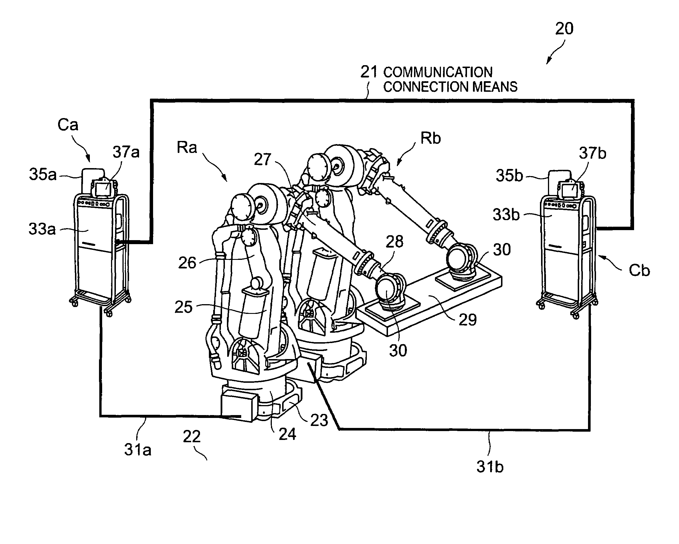
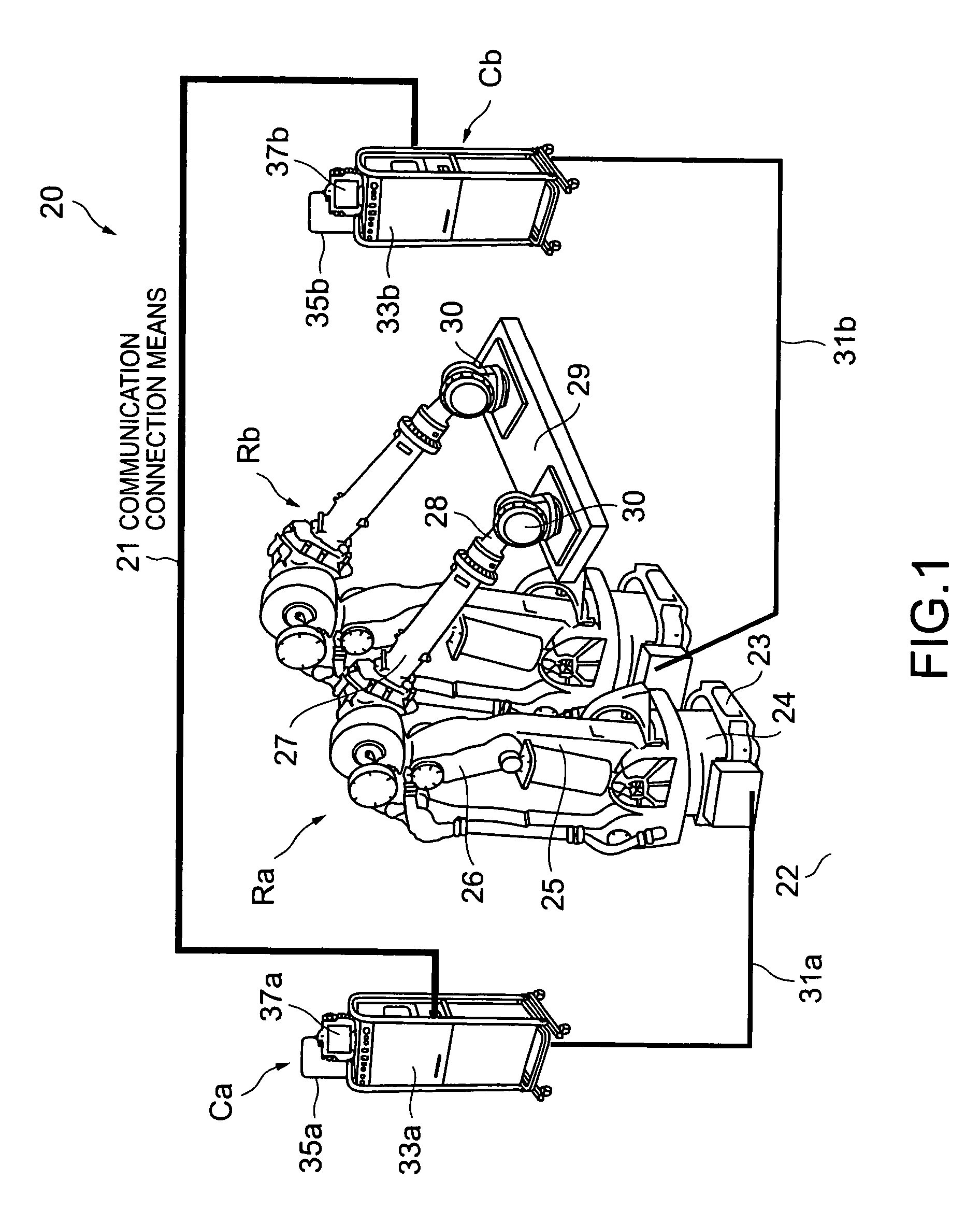
[0052]The robot cooperative control system (hereinafter, may be abbreviated just to “cooperative control system”) as an embodiment of the present invention shown in FIG. 1 includes a plurality of robots Ra and Rb (2 units in this embodiment), two control units Ca and Cb for independently controlling the robots Ra and Rb mutually and individually, and a communication connection means 21 for mutually connecting the control units Ca and Cb communicatably.

[0053]The robots Ra and Rb, as described as an example, are respectively realized by a 6-axis multi-joint robot in which a rotator 24 is installed on a base 23 installed on an almost horizontal floor 22 on a predetermined working stage in a factory at an interval, and on the rotator 24, a plurality of arms 25, 26, and 27 are installed angle-changeably round the axes, and a wrist 28 is installed on the tip of the arm on the free end side, and on the wrist 28, a hand 30 for removably holding a workpiece 29 is installed.

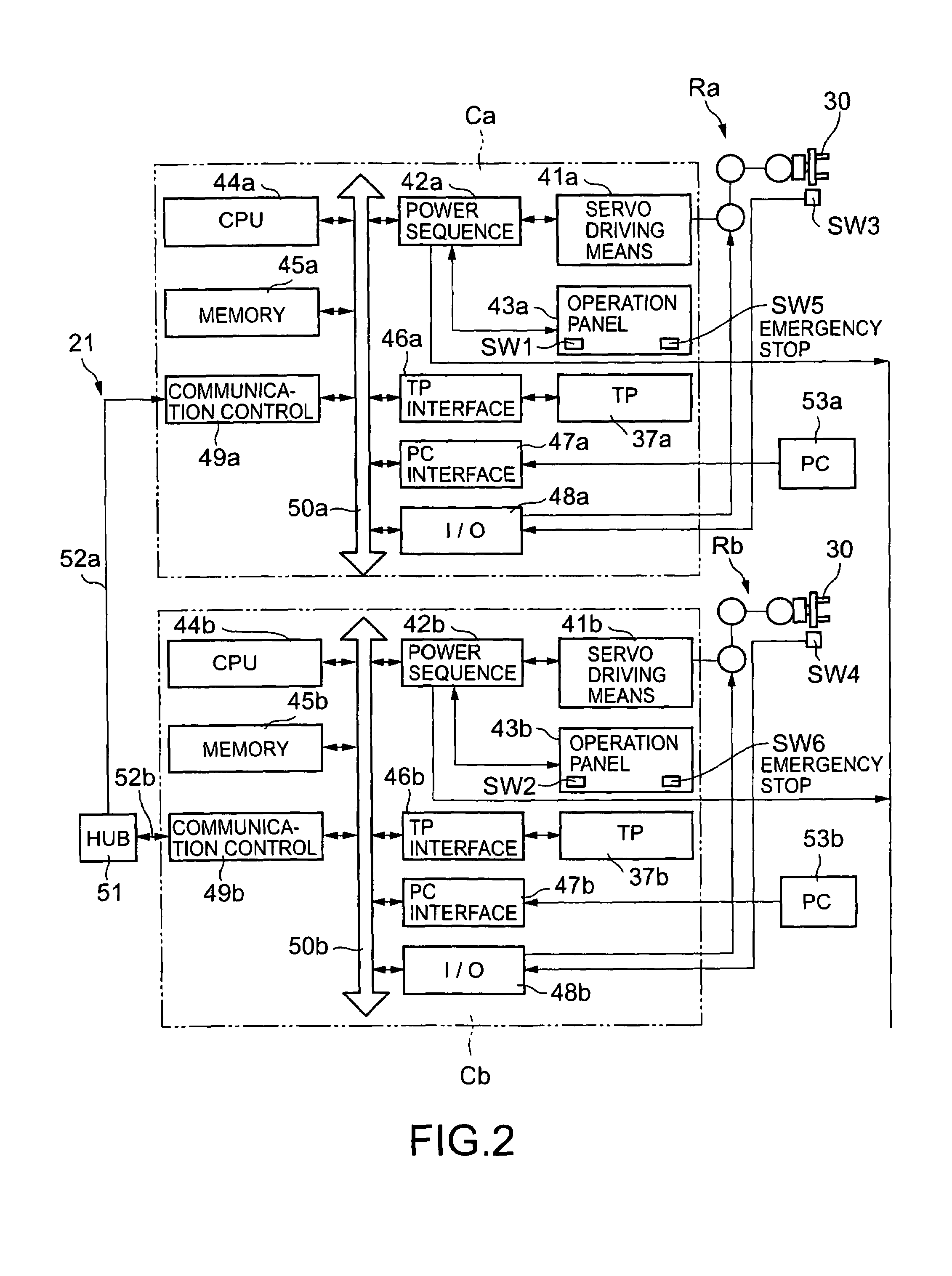
[0054]The control ...


PUM


Abstract

The present invention has a communication connection means (21) which mutually connects communicatably control units (Ca, Cb) for individually controlling operations of robots (Ra, Rb) to constitute a network, input means (37a, 37b) which are respectively installed in the control units and input operation instructions of the robots, and timing signal generation means (69a, 69b). The control units are selectively set to any one of an independent function execution mode, a master function execution mode, and a slave function execution mode, and among the control units, the control unit (Ca) to perform a master operation is set to the master function execution mode, and the residual control unit (Cb) is set to the slave function execution mode, and by correcting a minimum interruption period (Ts(b)) of the slave side control unit (Cb), a control time (ta11, ta12, ta13) to the master robot (Ra) of the master side control unit (Ca) is delayed by a predetermined time (T) to perform the cooperative operation. By doing this, the control units are always kept in the synchronized state, thus the operations of the robots can be prevented from variations.

Description

TECHNICAL FIELD [0001]The present invention relates to a cooperative control system of robots of which control units, which may be called robot controllers installed respectively in a plurality of robots, are connected to a communication network and the robots are operated cooperatively.BACKGROUND ART [0002]Conventionally, when a workpiece is heavy or large, to realize a cooperative operation for transferring the workpiece precisely and stably by maintaining the state of surely holding the workpiece by a plurality of robots via a plurality of preset teaching points extending from the departure point to the arrival point and interpolation points between the teaching points, a cooperative control system for cooperatively controlling each robot is adopted.[0003]In such a cooperative control system using a plurality of robots, a workpiece can be held at a plurality of positions according to the arrangement positions of the robots in the working space, so that even if the workpiece is la...

Claims


Application Information

Patent Timeline
Patent Type & Authority Patents(United States)
IPC IPC(8): G05B19/042B25J9/16B25J9/18B25J9/22B25J13/00
CPCB25J9/1682G05B2219/33097G05B2219/39141G05B2219/39124G05B2219/39051
Inventor MATSUMOTO, NAOYUKISANO, MASATOSHIMAEHARA, TSUYOSHISHIMOMURA, NOBUYASUUENO, TAKAHIRO
Owner KAWASAKI HEAVY IND LTD
Why Eureka
Try Eureka