Wire cooling device

A cooling device, wire technology, applied in the direction of filament/wire forming, textile and papermaking, fiber processing, etc., to achieve the effect of suppressing time variation

Active Publication Date: 2020-03-20
TMT MACHINERY INC
View PDF1 Cites 0 Cited by
  • Summary
  • Abstract
  • Description
  • Claims
  • Application Information

AI Technical Summary

Problems solved by technology

That is, the technology of Patent Document 1 does not actively improve the rectification effect by providing a plurality of porous plates compared with the case of a single porous plate.

Method used


Image

  • Wire cooling device
  • Wire cooling device
  • Wire cooling device

Examples


Embodiment Construction

[0025] Embodiments of the yarn cooling device of the present invention will be described below.

[0026] [Melt spinning device]

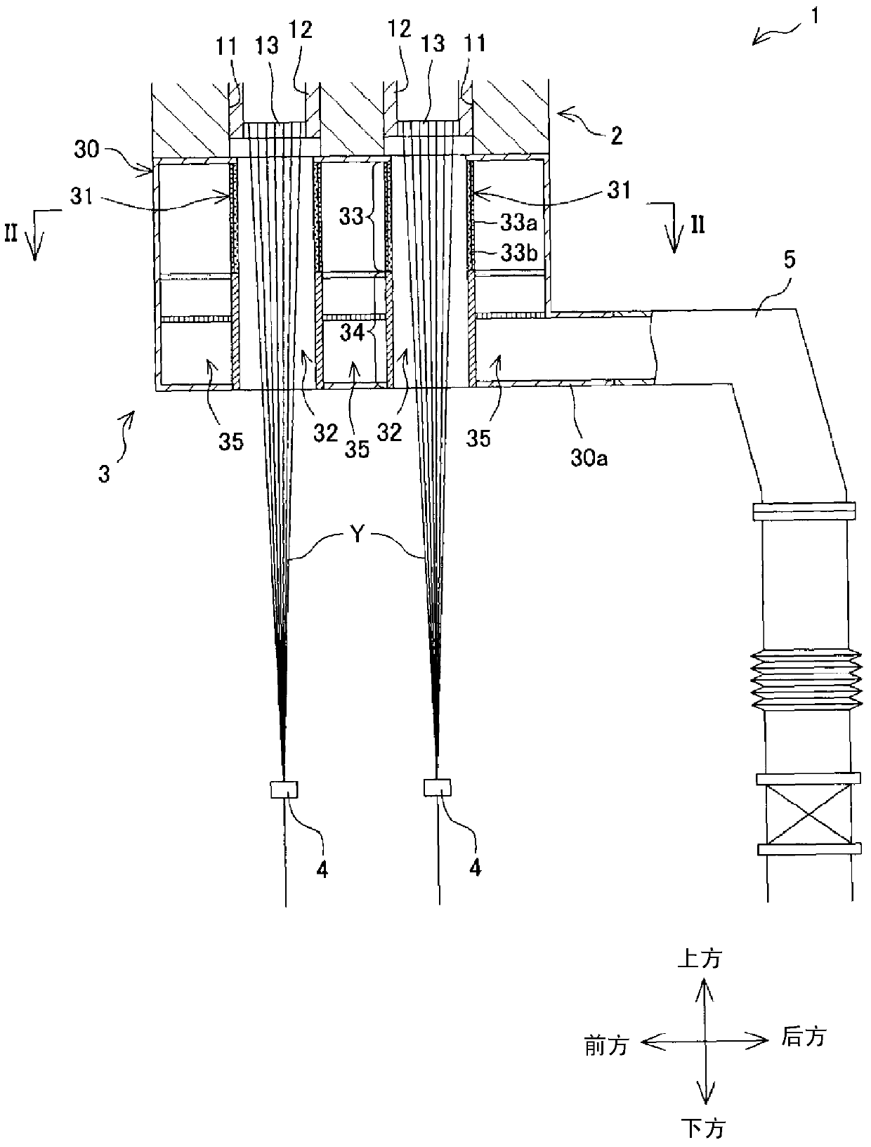
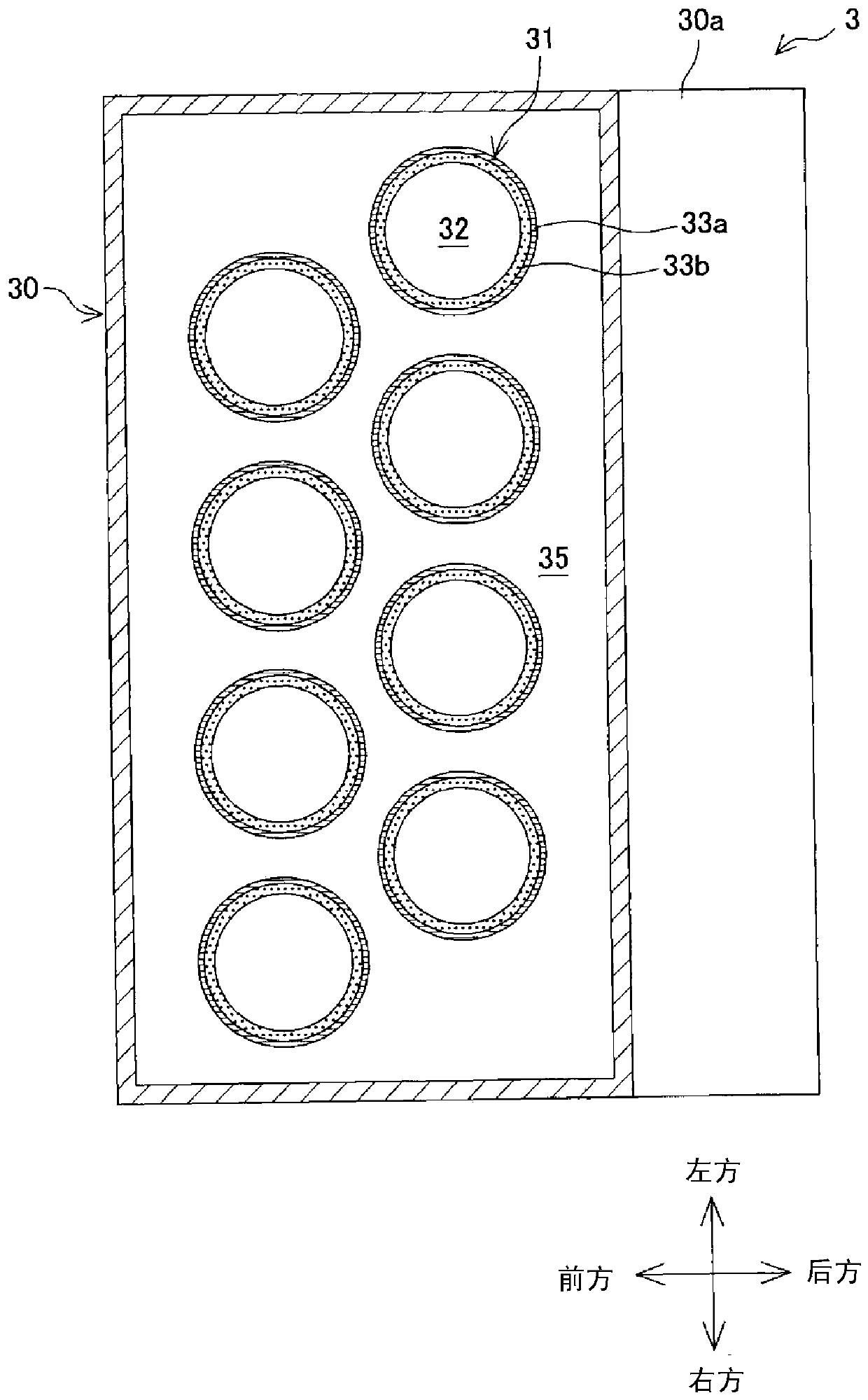
[0027] figure 1 It is a partial cross-sectional view of a melt spinning device equipped with a yarn cooling device of the present invention, figure 2 for figure 1 Ⅱ-Ⅱ line sectional view. Such as figure 1 As shown, the melt spinning device 1 includes a spinning beam 2, a yarn cooling device 3, an oil feeding device 4, and the like. The spinning beam 2 includes a plurality of unit housings 11 . In each pack case 11, a spin pack 12 is disposed, and in the spin pack 12 a melted material that becomes a yarn Y such as molten polyester is stored. A spinneret 13 is provided at the lower end of the spinneret 12, and the molten material stored in the spinneret 12 is spun out as a yarn Y from a plurality of through holes (not shown) formed in the spinneret 13. to the bottom. Among them, the plurality of spinnerets 13 are arranged in two rows in a ...


PUM


Abstract

An object is to actively improve the effect of flow adjustment in a yarn cooler including a plurality of porous plates, as compared with the configuration where a single porous plate is provided, and to effectively restrain a time variation in the flow of cooling air entering into a yarn running space. The yarn cooler includes: a first porous plate 36 disposed in a supply passage 35 where cooling air flows upward along an impassable section 34 of a cooling cylinder 31, the first porous plate 36 being configured to adjust the flow of the cooling air; and a second porous plate 37 disposed above and apart from the first porous plate 36 in the supply passage 35, the second porous plate 37 being configured to further adjust the flow of the cooling air having been adjusted by the first porous plate 36, and the thickness ratio of the second porous plate 37 is designed to be smaller than the thickness ratio of the first porous plate 36.

Description

technical field [0001] The present invention relates to a yarn cooling device for cooling the yarn spun downward from a spinneret. Background technique [0002] As a yarn cooling device for cooling the yarn spun from a spinneret, there is a device disclosed in Patent Document 1, for example. In this yarn cooling device, a buffer chamber through which cooling air flows upward is formed around a cylindrical member constituting a peripheral wall of the yarn running space, and the wire can be cooled by flowing cooling air from the buffer chamber into the yarn running space. Among them, if the cooling air flowing into the yarn running space has temporal fluctuations, uneven cooling may occur on the wires, which may degrade the quality of the yarns. Therefore, it is important to suppress the temporal fluctuations of the cooling air. Therefore, Patent Document 1 describes that a perforated plate (flow rectification member) is provided in the buffer chamber. especially image 3 (2...

Claims


Application Information

Patent Timeline
Patent Type & Authority Patents(China)
IPC IPC(8): D01D5/088D01D5/092
CPCD01D5/088D01D5/092
Inventor 泽田淳桥本欣三菊池纯川本和弘铃木淳平
Owner TMT MACHINERY INC
Why Eureka
Try Eureka