Electronic mail server with facsimile transmission on electronic mail transmission failure

a facsimile transmission and electronic mail technology, applied in the field of electronic mail server devices, can solve problems such as line busyness, and achieve the effect of reducing workload, reducing workload, and reducing workload on the communication terminal devices of transmitters

Inactive Publication Date: 2009-07-07
MURATA MASCH LTD
View PDF23 Cites 10 Cited by
  • Summary
  • Abstract
  • Description
  • Claims
  • Application Information

AI Technical Summary

Benefits of technology

This patent describes an improved email system that reduces the burden on users' computers and ensures reliable delivery of emails containing images or other attachments. It uses a combination of features such as error detection and automatic resending mechanisms to prevent failures in delivering important messages. Additionally, it allows for easy management of multiple user accounts and simplifies the overall administration of the email system.

Problems solved by technology

This patent describes a technical problem with current internet fax machines where if they fail to send an email containing images through the internet, they will automatically switch to sending them through a phone call instead - increasing their workload and potentially causing delays or errors during the transfer. Additionally, some emails may not include a notification of the failed transfer, making it difficult to quickly address any issues.

Method used


Image

  • Electronic mail server with facsimile transmission on electronic mail transmission failure
  • Electronic mail server with facsimile transmission on electronic mail transmission failure
  • Electronic mail server with facsimile transmission on electronic mail transmission failure

Examples


first embodiment

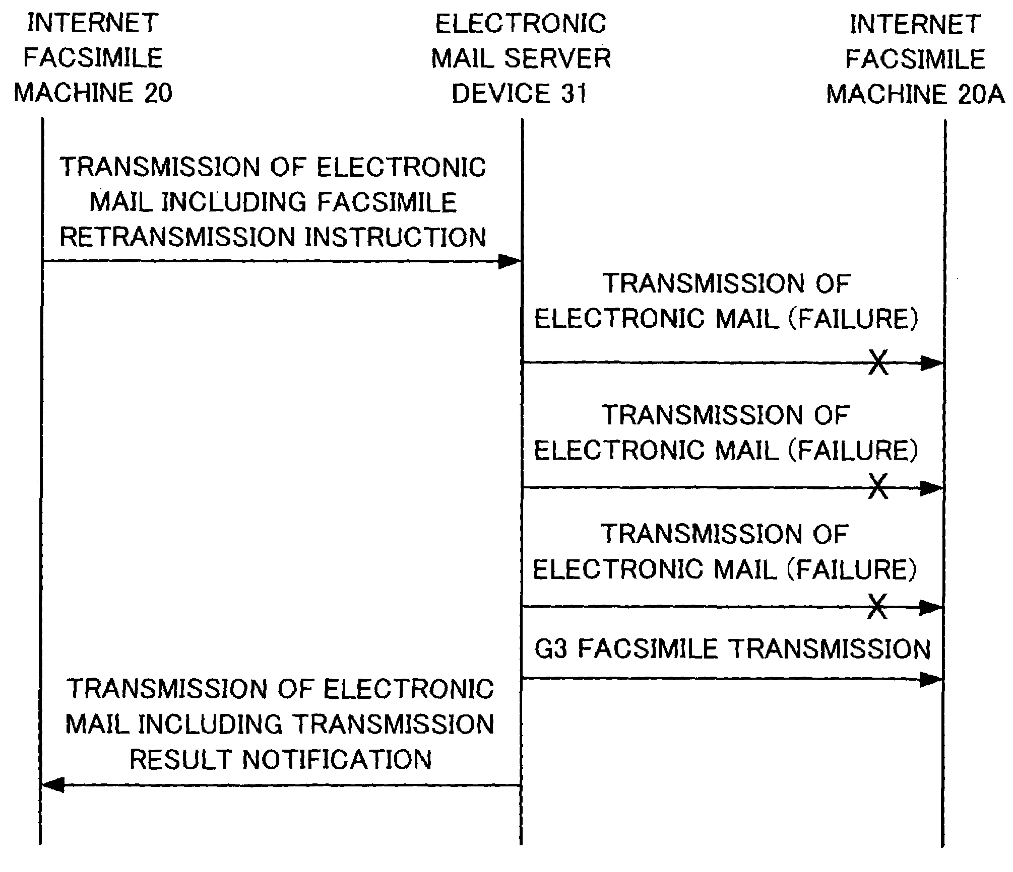
[0035]FIG. 4 is a sequence diagram showing an operation of each of the devices according to the present invention. In FIG. 4, first, the Internet facsimile machine 20 transmits an electronic mail to the electronic mail server device 31 via the LAN 30. The electronic mail contains image data as an attached file, and a facsimile retransmission instruction. An example of the electronic mail is shown in the following Chart 1.

(Chart 1) An example of transmitting electronic mail (including the facsimile retransmission instruction)

[0036]From: ifax1@sample.co.jp[0037]Date: Wed, Mar 14, 2001 16:04:22 +0900[0038]To: ifax2@sample.co.jp[0039]Subject: SAMPLE MAIL[0040]MIME-Version: 1.0[0041]Content-Type: multipart / mixed; boundary=″=_SAMPLE_=″--=_SAMPLE_=[0042]Content-Type: text / plain; charset=“us-ascii”[0043]Content-Transfer-Encoding: 7 bit[0044]Retry=(MAIL:3)(FAX:15)(3 min)[0045]--=_SAMPLE_=[0046]Content-Type: image / tiff; name=“faximage.tif”[0047]Content-Transfer-Encoding: base64[0048]Content-D...

second embodiment

[0058]FIG. 5 is a sequence diagram showing an operation of each of a number devices according to the present invention. In FIG. 5, first, the Internet facsimile machine 20 transmits an electronic mail to the electronic mail server device 31 via the LAN 30. The electronic mail includes an instruction of retransmission by relay forwarding, and image data attached as an attached file. An example of the electronic mail is shown in the above Chart 1. Next, the electronic mail server device 31 receives the electronic mail, and temporarily stores the data of the electronic mail in the RAM 107. Then, the electronic mail server device 31 attempts to transmit the electronic mail to the Internet facsimile machine 20A of the destination via the Internet 40. In this case, when the transmission fails for three times (when the transmission protocol by the SMTP does not end normally), in accordance with the instruction for facsimile retransmission, the relay electronic mail address corresponding to...


PUM


Abstract

To reduce workload on an Internet facsimile machine on the transmission side, and to execute a retransmission processing promptly and reliably, an electronic mail server device includes a function for receiving an electronic mail, a function for transmitting the received electronic mail to the Internet facsimile machine of a destination via the Internet, and a function for carrying out a facsimile transmission of the image data via a public telephone network. The electronic mail server device also includes a RAM which stores an address/number corresponding table which corresponds the electronic mail address and the facsimile number of the Internet facsimile machine of the destination. When receiving the electronic mail including the image data, and failing to transmit the electronic mail including the image data to the Internet facsimile machine of the destination, a main control unit carries out a facsimile transmission of the image data of the electronic mail to the Internet facsimile machine of the destination via the public telephone network in accordance with the facsimile number corresponding to the electronic mail address of the Internet facsimile machine of the destination.

Description


Claims


Application Information

Patent Timeline
Owner MURATA MASCH LTD
Why Eureka
Try Eureka