
Motion control apparatus for hospital bed

a technology for controlling apparatus and hospital beds, which is applied in the direction of wheelchair/patient conveyance, transportation and packaging, cabinets, etc., can solve the problems of wear and damage of the shoe surface, and achieve the effect of simplifying the overall operation and simplifying the operation of the user

Inactive Publication Date: 2009-07-14
SIGMA CARE DEV
View PDF11 Cites 12 Cited by
  • Summary
  • Abstract
  • Description
  • Claims
  • Application Information

AI Technical Summary

Benefits of technology

"The present invention is a hospital bed with separate pedals for braking and orientation. This design makes the bed easier to operate and more ergonomic. The middle pedal is the only one needed to brake or disable orientation, making the overall operation simpler. The technical effect of this invention is to improve the efficiency and ease of use of hospital beds."

Problems solved by technology

Such operation does not conform to good ergonomics and may cause dangerous reactions.
Although the operation is done, the surface of the shoe becomes worn, and the user wants to avoid this.

Method used


Image

  • Motion control apparatus for hospital bed
  • Motion control apparatus for hospital bed
  • Motion control apparatus for hospital bed

Examples


Embodiment Construction

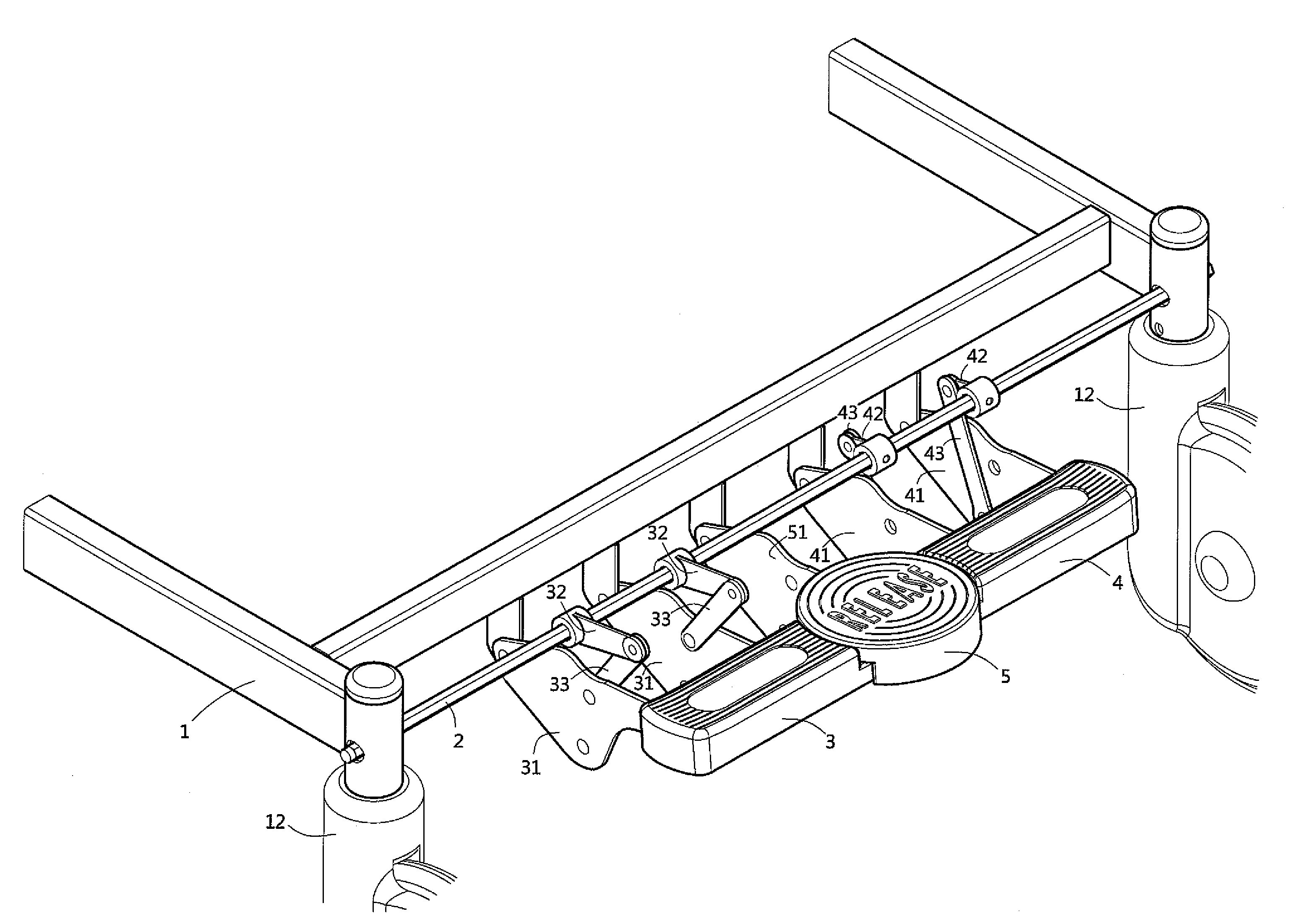
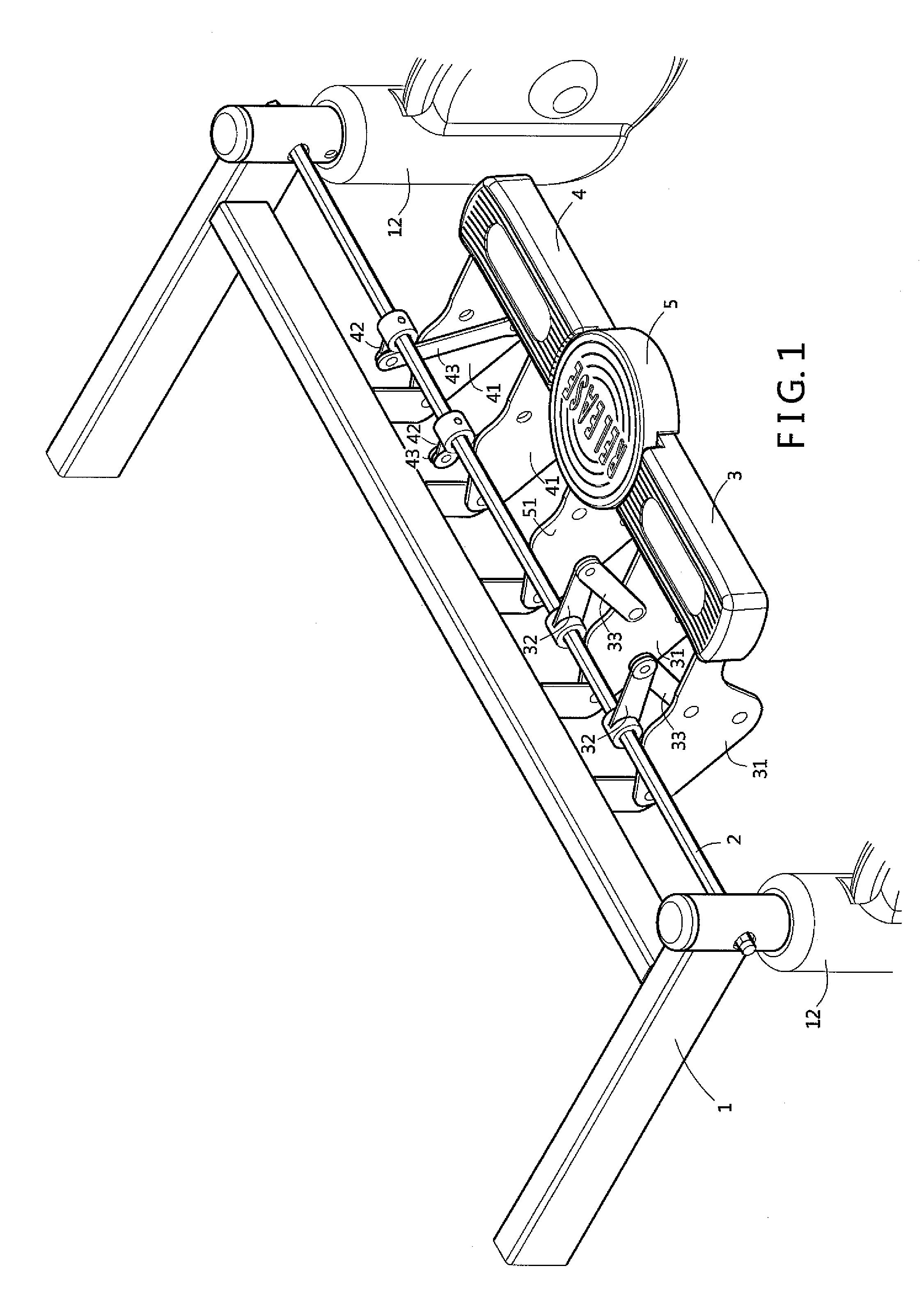
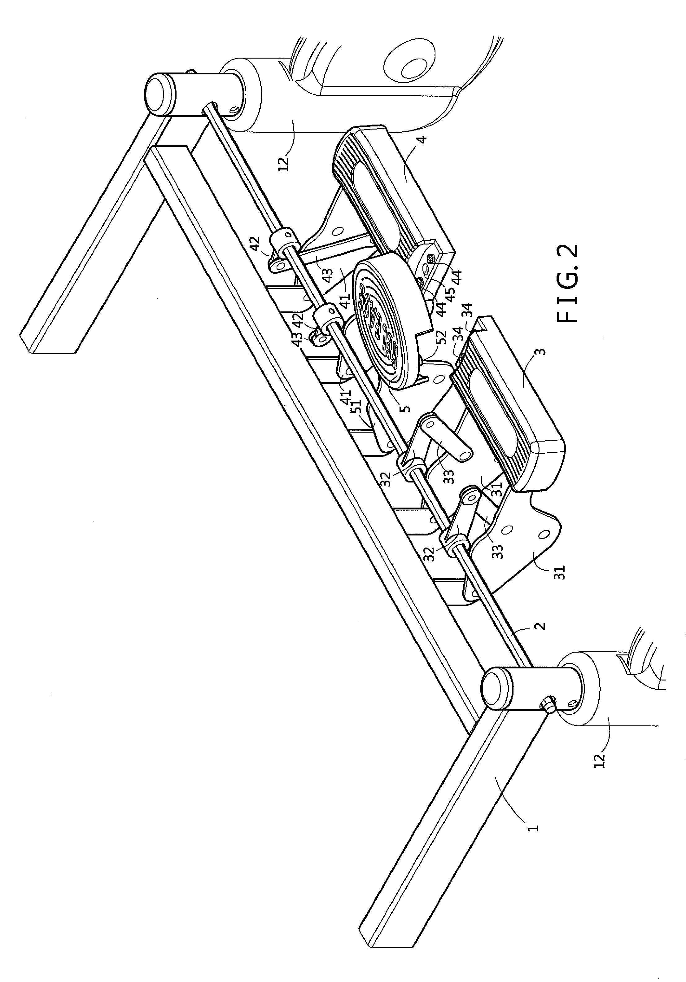
[0016]Please refer to FIG. 1, FIG. 2 and FIG. 3. The hospital bed is provided with a plurality of wheel modules 12. An axial shaft 2 passes through wheel modules 12 on two sides. The axial shaft 2 turns different directions to control the braking or orientation of the wheel modifies 12. The two axial shafts 2 at the front and rear ends of the chassis can turn simultaneously by a coupler (not shown in the figure). A plurality of swing racks 31, 41 and 51 are pivotally connected at predetermined locations on the chassis 1, and three pedals 3, 4 and 5 are pivotally fixed thereto. Driving components 32 and 42 pass through the axial shaft 2 corresponding to the swing racks 31 and 41 of the pedals 3 and 4 on two sides. The driving components 32 and 42 are in opposite directions, that is, the driving component 42 is towards the inside of the hospital bed while the driving component 32 is towards the outside of the hospital bed. Couplers 33 and 43 are pivotally connected between driving com...


PUM


Abstract

A motion control apparatus for a hospital bed includes an axial shaft passing through two wheel modules. Three pedals capable of swinging upwardly and downwardly are pivotally disposed on the chassis in parallel. Driving components are fixedly disposed in opposite directions on the axial shaft corresponding to the pedals on two sides. A coupler is disposed between each driving component and pedal. When one of the two pedals on the two sides is stepped on downwardly, the axial shaft is driven to turn and results in braking of the wheel modules. When the middle pedal is stepped on downwardly, the other pedals gathered together swing downwardly at the same time, and the pedals on the two sides come to lean on the middle pedal at the same time and stop, resulting in disabling of the braking or orientation function.

Description

BACKGROUND OF THE INVENTION[0001]1. Field of the Invention[0002]The present invention relates to pedals used for stepping downwardly thereon to control the braking and orientation of a hospital bed respectively, and a returning pedal disposed between the two pedals for disabling the functions of braking or orientation.[0003]2. Description of the Related Art[0004]The assignee of the present invention has a patent “Braking Apparatus for Hospital Bed” with Taiwanese Application No. 095204622 and Taiwanese Patent No. TW296695Y. The apparatus is mainly comprised of wheel modules that are free to change direction and are disposed at the four corners of the chassis of a movable hospital bed. Two axial shafts are respectively disposed between the two adjacent wheel modules at the front and the rear ends of the hospital bed. By turning the axial shaft in different directions and at various angles, the braking of the wheel module will be active or inactive, or at least one wheel module will b...

Claims


Application Information

Patent Timeline
Patent Type & Authority Patents(United States)
IPC IPC(8): A61G7/08B62B5/04
CPCA61G7/05A61G2007/0528A61G7/0528
Inventor HE, TSAI-TIEN
Owner SIGMA CARE DEV
Learn More