Gas sensor with increased water-incursion resistance and method of operating gas sensor

a gas sensor and water-incursion resistance technology, applied in the field of gas sensors, can solve the problem of not being able to establish direct fluid communication between the inner-shell bottom opening and the outer-shell bottom opening, and achieve the effect of increasing water-incursion resistance and reducing the response of the gas sensor

Active Publication Date: 2009-07-14
DENSO CORP
View PDF11 Cites 6 Cited by
  • Summary
  • Abstract
  • Description
  • Claims
  • Application Information

AI Technical Summary

Benefits of technology

[0034]If the number of outer-shell bottom wall openings is less than 2, then, a need arises to install the gas sensor on the exhaust gas pipe upon specifying directivity on installation, resulting in practical disadvantage. In addition, the introduction and expelling of measuring gases become inefficient, causing a drop in response of the gas sensor. Moreover, if the number of outer-shell bottom wall openings is greater than 7, then, a probability increases for the water droplets to intrude the inside of the inner shell. This results in not only a drop in advantage of the present invention but also a decrease in a flow speed of the measuring gas stream with a resultant droop in response of the gas sensor.
[0035]With the gas sensor of the present embodiment, the plurality of outer-shell bottom wall openings are formed on the outer-shell bottom wall in a circular area outside an intersecting circle between extended lines extending along the tapered portion of the leading end portion of the inner shell and the outer-shell bottom wall.
[0036]With the outer-shell bottom wall openings formed in such a circular area, the outer-shell bottom wall openings are located in areas on extensions of the measuring gas stream passing along a tapered surface of the leading end portion of the inner-shell. This makes it easy for the water droplets in measuring gases to be expelled from the outer-shell bottom wall openings. Accordingly, the concentration sensing element is less susceptible to water-incursion.
[0037]With the gas sensor of the present embodiment, each of the outer-shell bottom wall openings may be preferably formed in a circle shape with a diameter of a value equal to or greater than 1.0 mm and equal to or less than to 2.0 mm.
[0038]With the outer-shell bottom wall openings formed in such diameters, the gas sensor has an optimum response, while allowing the concentration sensing element to have increased water-incursion resistance.
[0039]If the outer-shell bottom wall openings have diameters less than 1.0 mm, then, the exhaust gas stream is hard to be admitted through the outer-shell sidewall openings and expelled through the outer-shell bottom wall openings, resulting in a drop in response of the gas sensor.

Problems solved by technology

Further, no direct fluid communication is established between the inner-shell bottom opening and the outer-shell bottom wall openings.

Method used


Image

  • Gas sensor with increased water-incursion resistance and method of operating gas sensor
  • Gas sensor with increased water-incursion resistance and method of operating gas sensor
  • Gas sensor with increased water-incursion resistance and method of operating gas sensor

Examples


first embodiment

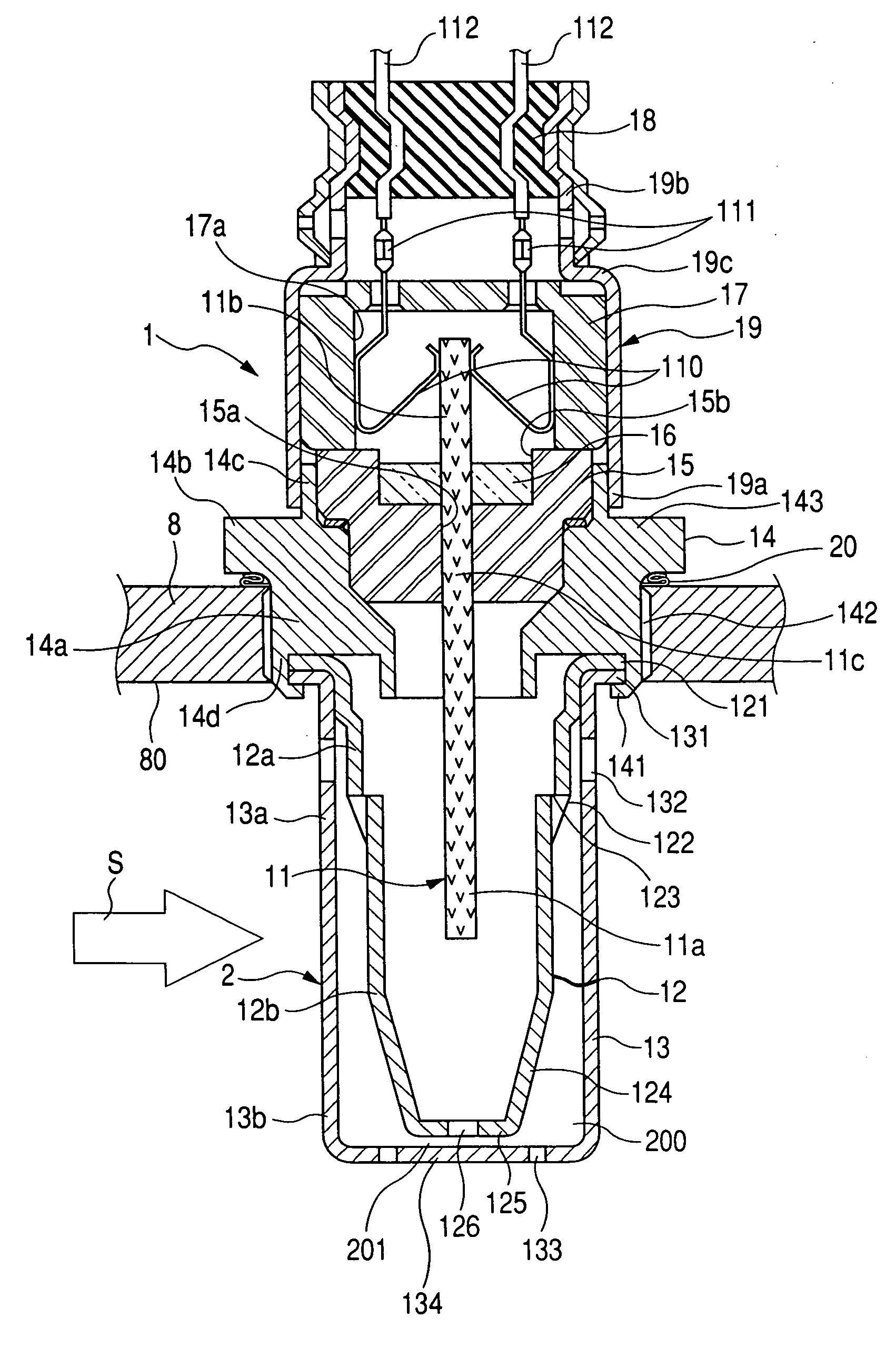
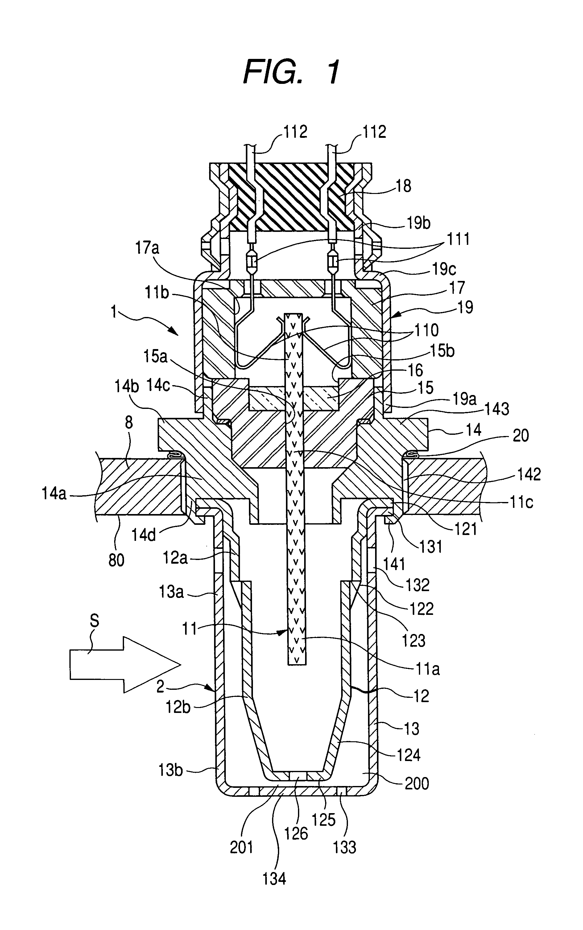
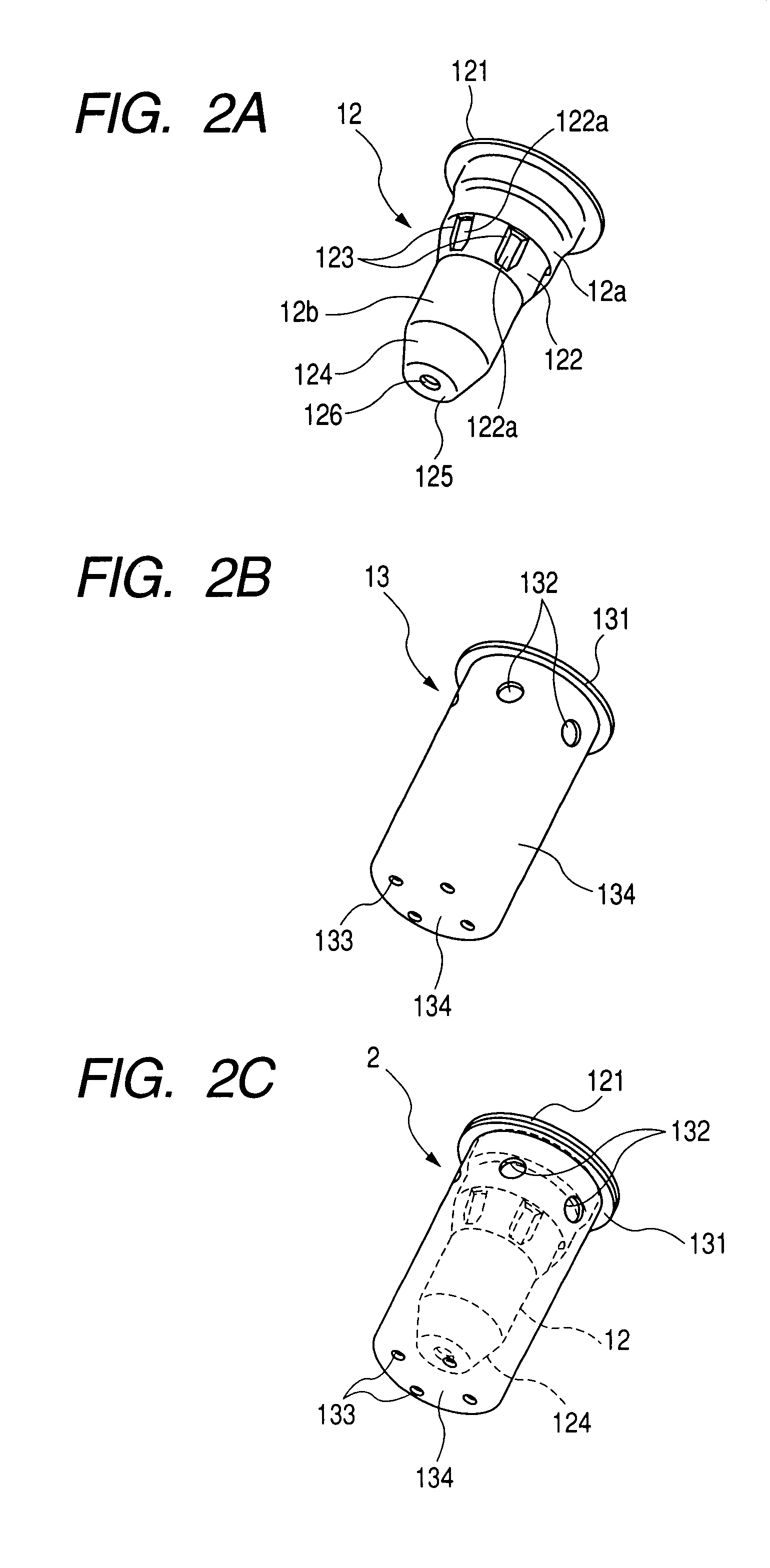
[0073]A gas sensor of a first embodiment according to the present invention is described below in detail with reference to FIGS. 1 and 2.

[0074]As shown in FIG. 1, the gas sensor 1 comprises a gas sensing element 11 for detecting a concentration of a specified gas component in measuring gases, a housing 14 for fixedly supporting the gas sensing element 11 to be exposed to a measuring gas flow passage 80, and a cover body 2 made of, for instance, stainless steel or the like for covering the housing 14 and a leading end portion 11a of the gas sensing element 11 to be exposed to measuring gases.

[0075]The housing 14 includes a housing body 14a whose outer periphery is formed with a tool-fitting portion 14b in the form of a housing nut portion 143 with which a tool (not shown) is engageable, an upper cylindrical portion 14c axially extending upward from the housing body 14a, and a lower cylindrical portion 14d extending downward from the housing body 4a. The tool-fitting portion 14b is fo...


PUM

PropertyMeasurementUnit
diameteraaaaaaaaaa
diameteraaaaaaaaaa
temperatureaaaaaaaaaa

Abstract

A gas sensor and a related method operating are disclosed as having a concentration sensing element for detecting a concentration of a specified gas component in the measuring gases. A housing supports the concentration sensing element and a cover body structure, which includes an inner shell and an outer shell for surrounding a leading end portion of the concentration sensing element in an area exposed to a measuring gas flow passage. An annular sideways clearance is defined between the inner shell and the outer shell. The inner shell has a sidewall whose upper area is formed with inner-shell sidewall openings and a bottom wall formed with an inner-shell bottom wall opening. The outer shell has a sidewall formed with outer-shell sidewall openings and a bottom wall having outer-shell bottom wall openings formed in an outer circumferential area radially outside the inner-shell bottom wall opening.

Description

CROSS REFERENCE TO RELATED APPLICATIONS[0001]This application is related to Japanese Patent Application Nos. 2006-199073 and 2006-337819, filed on Jul. 21, 2006 and Dec. 15, 2006, respectively, the contents of which are hereby incorporated by reference.BACKGROUND OF THE INVENTION[0002]1. Technical Field of the Invention[0003]The present invention relates to gas sensors for detecting a concentration of a specified gas component in measuring gases of, for instance, automotive engines or the like and, more particularly, to a gas sensor having a cover body structure for protecting a gas sensing element.[0004]2. Description of the Related Art[0005]With the development of automotive engines, attempts have heretofore been made to provide a gas sensor mounted on an exhaust pipe of an internal combustion engine such as an automotive engine. The gas sensor detects a concentration of, for instance, a specified gas component such as oxygen in measuring gases to output a detection signal. The de...

Claims


Application Information

Patent Timeline
Patent Type & Authority Patents(United States)
IPC IPC(8): G01N9/00
CPCG01N27/4077
Inventor YAMADA, KOUHEI
Owner DENSO CORP
Why Eureka
Try Eureka