Transport installation with aerial rope conveying chairs and gondola cars

a technology of conveying chairs and transportation, which is applied in the direction of transportation and packaging, rope railways, train hauling devices, etc., can solve the problems of reducing user throughput, affecting the safety of users on board, and affecting the safety of passengers,

Inactive Publication Date: 2009-07-14
POMAGALSKI SA
View PDF28 Cites 12 Cited by
  • Summary
  • Abstract
  • Description
  • Claims
  • Application Information

AI Technical Summary

Benefits of technology

[0013]The object of the invention is to remedy the above shortcomings by proposing an aerial ropeway transport installation of the type mentioned in the preamble of the main claim which achieves an increased user throughput and which improves the diversity of combination of the vehicles.
[0015]This arrangement enables the time interval between two successive vehicles of the same type to be adapted according to the physical distance necessary between two vehicles of the same type to prevent them from bumping into one another in the curve of the slowest part of the run-through section. It thereby becomes possible to provide groups of successive cars without this considerably reducing the user throughput. The cars are farther apart from one another whereas the chairs are closer to one another in comparison with the constant speed regulation of the prior art which resulted from a compromise.
[0017]A rate regulating section according to the invention therefore has the object of optimizing the time interval between two successive vehicles according to the physical distance just necessary between these two vehicles, depending on their respective type, to prevent them from bumping into one another in the curve of the slowest part of the run-through section.

Problems solved by technology

The minimum value of the time interval between two vehicles is conditioned by the physical distance necessary between these two vehicles to prevent them from bumping into one another in the curve of the slowest part of the run-through section, which would be dangerous for people outside the vehicles and uncomfortable for the users on board.
But these known installations are not completely satisfactory as far as the user throughput is concerned.
In addition, it is impossible to configure the installation in such a way as to have two successive cars without this considerably reducing the user throughput for, in this case, the time interval between vehicles is increased.
The diversity of combination of the vehicles is therefore very limited if a correct user throughput is to be preserved.

Method used


Image

  • Transport installation with aerial rope conveying chairs and gondola cars
  • Transport installation with aerial rope conveying chairs and gondola cars
  • Transport installation with aerial rope conveying chairs and gondola cars

Examples


Embodiment Construction

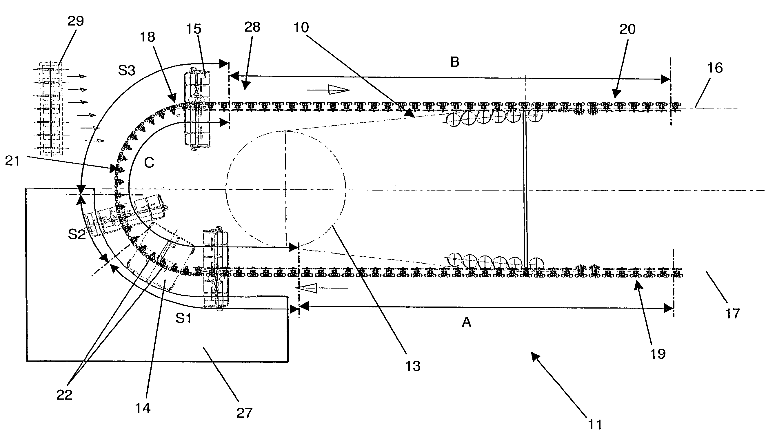
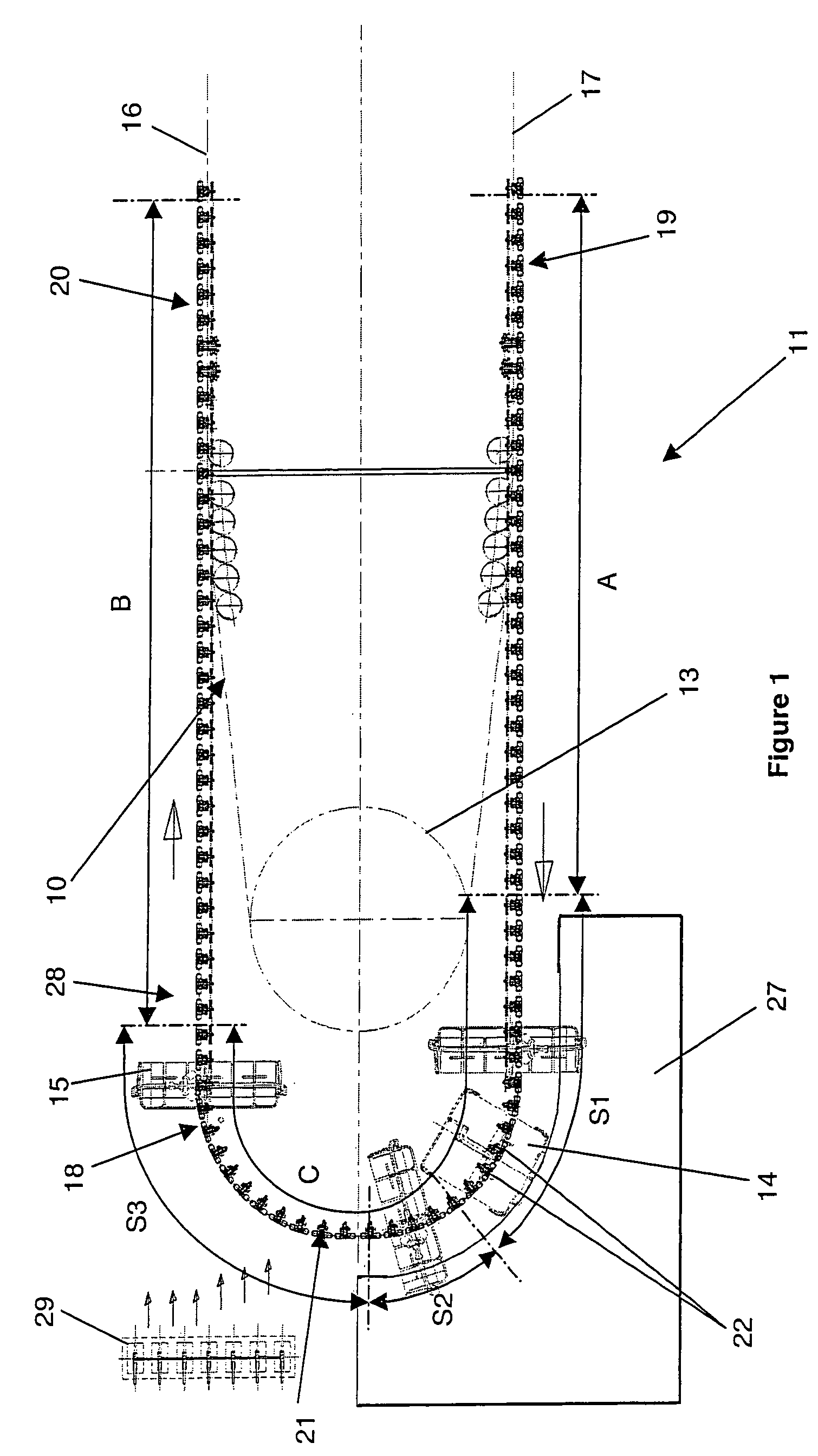
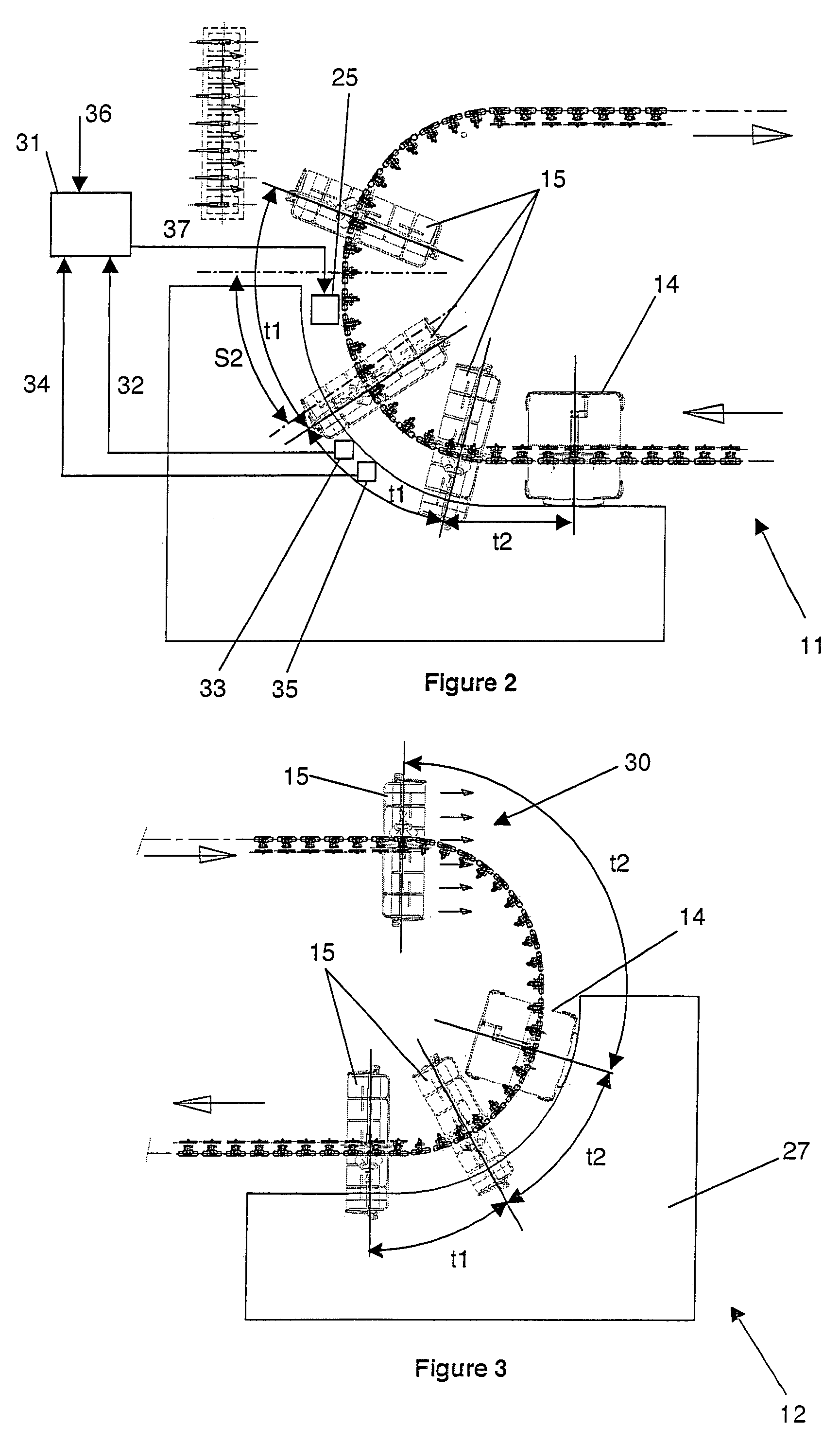
[0023]In the figures, an aerial rope 10 of a transport installation extends in a closed loop between two loading / unloading terminals 11, 12, respectively bottom and top terminals, passing in the terminals on bull-wheels 13, one whereof, the drive bull-wheel, drives the rope 10 continuously. The rope 10 supports gondola cars 14 and chairs 15 coupled by detachable grips staggered along the rope in a predetermined combination. The transport installation can comprise other intermediate terminals located along the up-line 16 and the down-line 17 of the rope 10 for loading and / or unloading passengers to and from the vehicles 14, 15.

[0024]FIGS. 1 and 2 illustrate the bottom terminal 11. At the entry to the terminal 11, the vehicles are detached from the down-line 17 and run on a transfer circuit 18 at reduced speed in the terminal 12 until they reach the up-line 16. A slowing-down device 19 slows down the vehicles 14, 15 detached from the rope 10, whereas at the exit a propelling device 20...


PUM


Abstract

A transport installation with a continuous running aerial rope supports chairs and gondola cars coupled by detachable grips. The rope extends in a closed loop between two bull-wheels, with an up-line and a down-line. The installation presents loading / unloading terminals provided at least at the ends of said lines. One of the terminals comprises a transfer circuit connecting the up-line and the down-line, with a slowing-down section equipped with a slowing-down device, a speeding-up section equipped with a propelling device, connected by a run-through section with a low running speed equipped with a driving device of the vehicles. The transfer circuit comprises a continuous running speed regulating section equipped with a speed regulating means that is able to vary the time required by the cars and the chairs to pass through the speed regulating section, to impose a first predetermined running speed of the cars and a second predetermined running speed of the chairs.

Description

BACKGROUND OF THE INVENTION[0001]The invention relates to a transport installation with a continuous running aerial rope, supporting vehicles composed of chairs and gondola cars coupled by detachable grips and staggered along the rope in a predetermined combination and with a predetermined running rate, said rope extending in a closed loop between two bull-wheels, with an up-line and a down-line, said installation having loading / unloading terminals provided at least at the ends of said lines, at least one of the loading / unloading terminals comprising:[0002]detachment means, on entry, to detach the grips from the rope,[0003]engagement means, on exit, to recouple the grips and the rope,[0004]a transfer circuit connecting the up-line and the down-line of the rope, with a slowing-down section equipped with a slowing-down device, and a speeding-up section equipped with a propelling device, connected by a run-through section with a low running speed equipped with a driving device of the v...

Claims


Application Information

Patent Timeline
Patent Type & Authority Patents(United States)
IPC IPC(8): B61B12/00
CPCB61B12/105B61B12/022
Inventor HUARD, JEAN-PAULREVENANT, NICOLAS
Owner POMAGALSKI SA
Why Eureka
Try Eureka