Height-adjustable furniture leg

a furniture leg and height adjustment technology, applied in the direction of tables, household objects, variable height tables, etc., can solve the problems of difficult to remove dirt, present unpleasant appearance, and collect dirt on the step

Active Publication Date: 2009-07-14
KESSELBOHMER PRODN
View PDF16 Cites 18 Cited by
  • Summary
  • Abstract
  • Description
  • Claims
  • Application Information

AI Technical Summary

Benefits of technology

[0005]In the furniture leg according to the invention, the exterior side of the external tube of the lifting column passes at least over most of its circumference, preferably about the entire circumference, continuously into the exterior side of the fastening part of the foot. In this way, at the transition from the foot into the lifting column no deposit location for dirt is formed. Instead, the topside of the foot has a continuous transition into the exterior side of the external tube. This continuous transition between foot and lifting column can be cleaned simply and without problems.
[0007]The external tube is advantageously centered on the fastening part of the foot so that the external tube in a simple way can be aligned precisely relative to the foot during assembly.
[0010]The fastening part surrounds advantageously a recess in the foot. Advantageously, the interior tube, when in its lower position, projects into the recess. When the foot in the area of the fastening part is configured to be thicker in the lifting direction of the lifting column, the recess in the fastening part or in the foot can be relatively large so that the interior tube in its lower position can be retracted relatively far into the recess. This contributes in an advantageous way to a minimal height of the lifting column in the lower end position. The internal tube can thus have a sufficiently large length so that the lifting column has a great height in the extended position of the internal tube.
[0012]Advantageously, the bottom of the recess in the end face of the fastening part has a spacing from the bottom of the recess of the foot which spacing is greater, advantageously multiple times greater, than the projecting portion of the fastening part projecting past the topside of the foot. This projecting portion can be, for example, three to four times the thickness of the foot. In this way, the foot, on the one hand, can still be relatively thin but can still enable a great lifting stroke of the lifting column.

Problems solved by technology

The step not only presents an unpleasant appearance but also leads to dirt collecting on the step which dirt is difficult to remove.

Method used


Image

  • Height-adjustable furniture leg
  • Height-adjustable furniture leg
  • Height-adjustable furniture leg

Examples


Embodiment Construction

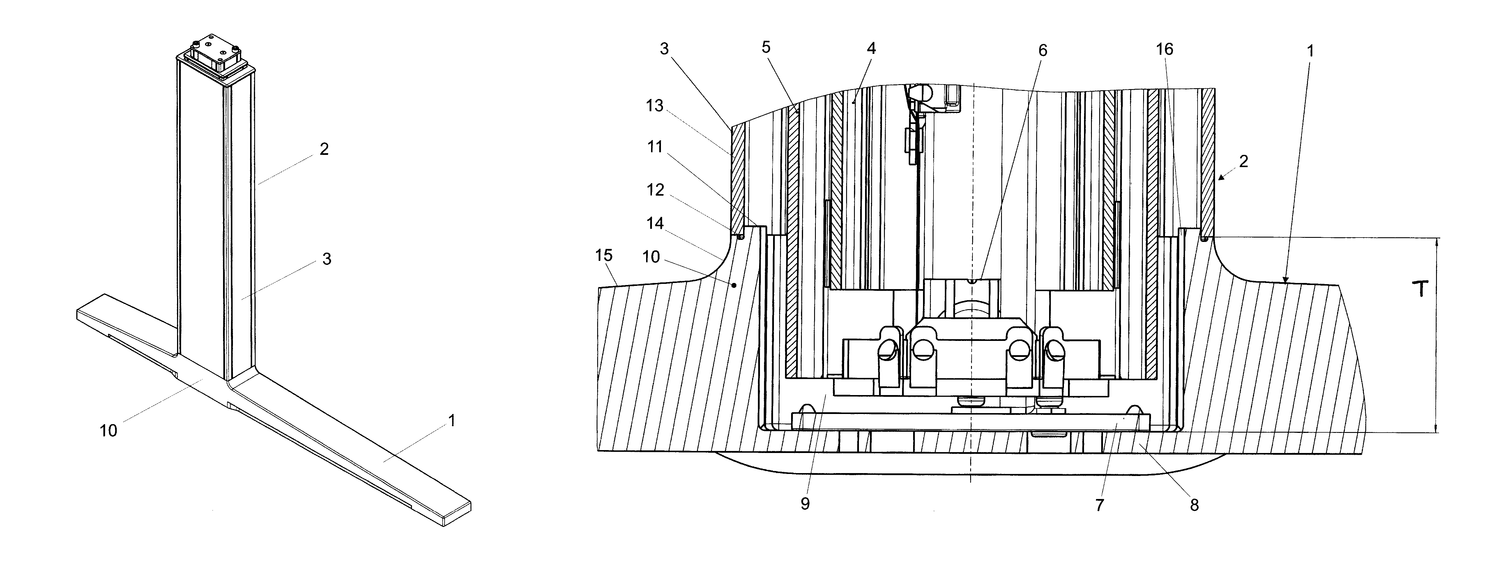
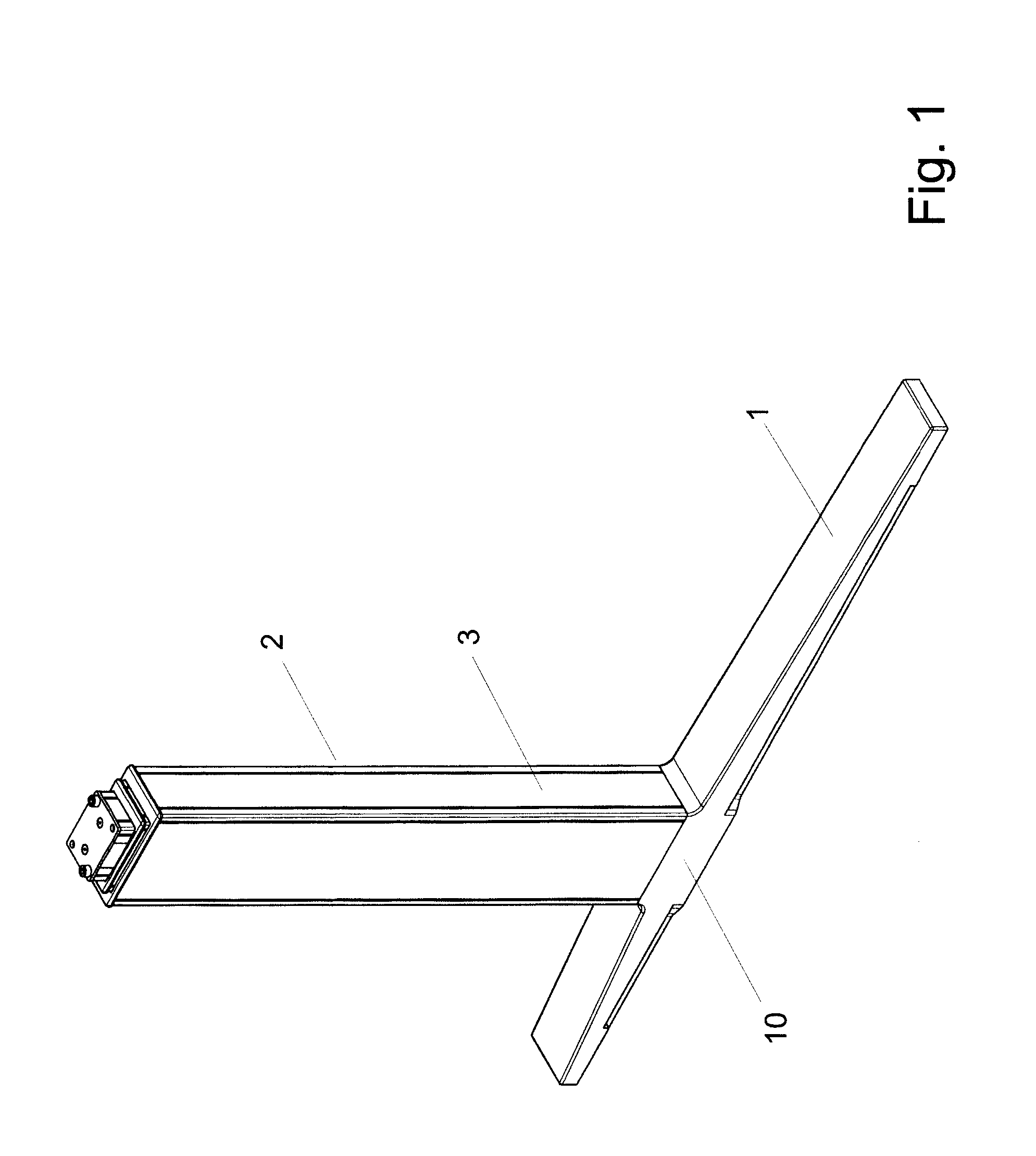
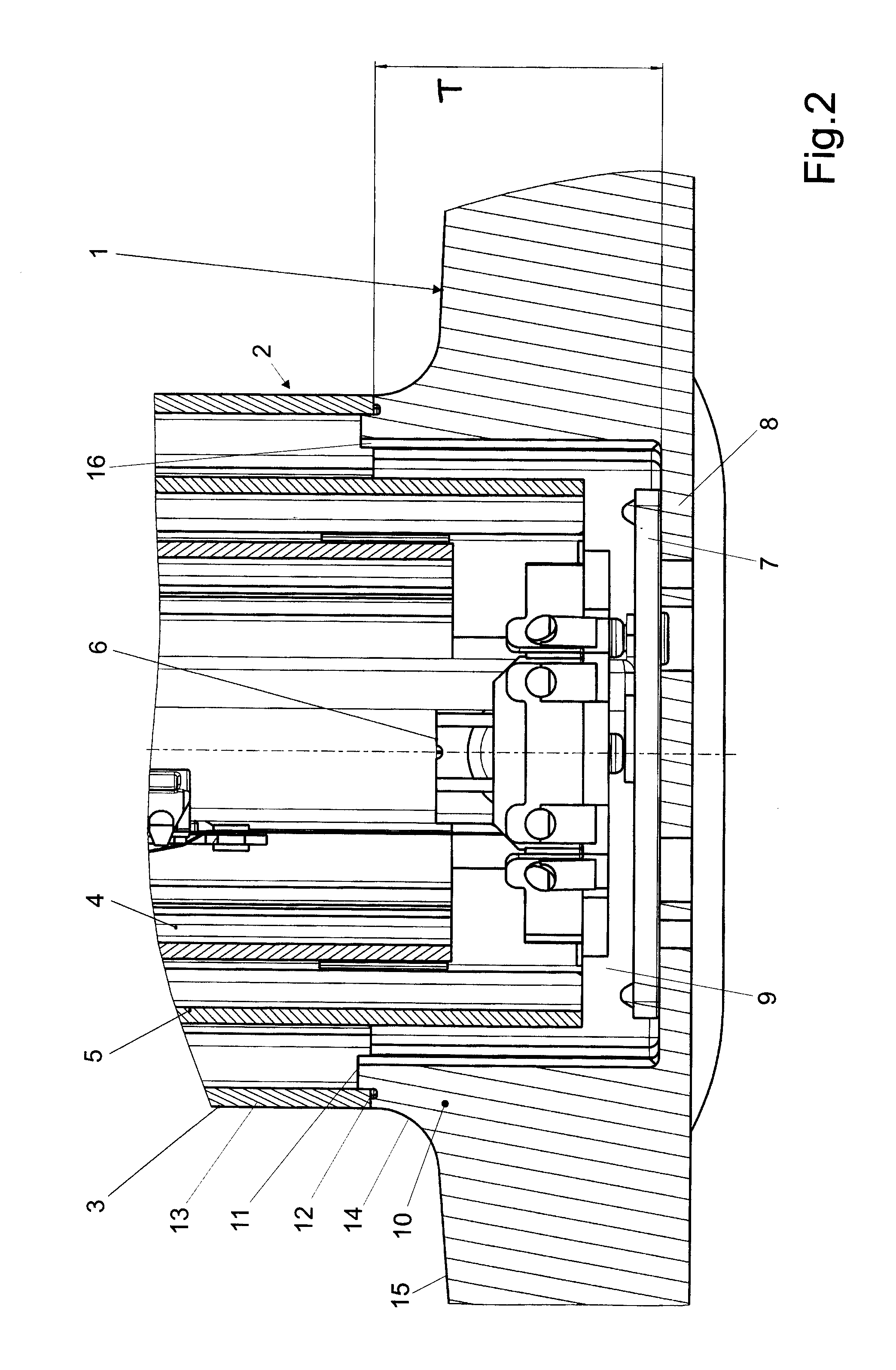
[0017]The furniture leg can be utilized in connection with tables of any kind, chairs, organ benches, and the like. Depending on the type of the piece of furniture, two or several furniture legs can be used for the respective piece of furniture. The furniture leg has the foot 1 which in the embodiment is an elongate foot rail. The foot 1 can also have any other suitable shape. A column 2 projects perpendicularly from the foot 1 and is embodied as a telescopic column. It has an external tube 3 attached to the foot 1. The external tube 3 surrounds at least one internal tube 4. In the illustrated embodiment, between the external tube 3 and the internal tube 4 there is a central tube 5. The tubes 3 to 5 are inserted into one another in a telescoping fashion and are axially moved relative to one another as is known in the art. The bearings that are provided between the tubes 3 to 5 are not illustrated in FIG. 2. The drive 6 is arranged in the column 2 for a telescoping driving action; th...


PUM


Abstract

The furniture leg has a foot from which a lifting column projects transversely that comprises an external tube and an internal tube that is telescopingly movable relative to the external tube. The external tube is attached to a fastening part of the foot. In order to configure the furniture leg in such a way that the foot and the lifting column can be connected to one another such that deposit locations for dirt and the like are not formed, the exterior side of the external tube at least over most of its circumference passes continuously into the exterior side of the fastening part. In this way, at the transition from the foot to the lifting column no deposit location for dirt is formed. The furniture leg is suitable for tables of any kind, chairs, organ benches and the like.

Description

BACKGROUND OF THE INVENTION[0001]The invention concerns a height-adjustable furniture leg with at least one foot from which a lifting column projects transversely that comprises an external tube and at least one internal tube that can be moved relative to the external tube telescopingly, the latter being connected to a fastening part of the foot.[0002]Height-adjustable furniture legs are known, for example, for worktables where the tabletop is to be adjusted to the right height. The lifting column is attached to the foot wherein at the transition from the foot or its fastening part to the lifting column a step is formed that is more or less large. The step not only presents an unpleasant appearance but also leads to dirt collecting on the step which dirt is difficult to remove.[0003]It is an object of the invention to configure the furniture leg of the aforementioned kind such that the foot and the lifting column are connected to one another such that deposit locations where dirt an...

Claims


Application Information

Patent Timeline
Patent Type & Authority Patents(United States)
IPC IPC(8): F16M11/26A47B9/00
CPCA47B9/20A47B9/04
Inventor KODER, MICHAEL
Owner KESSELBOHMER PRODN
Why Eureka
Try Eureka