Multifunctional armrest assembly for chair

a multi-functional, armrest technology, applied in the direction of chairs, vehicle components, vehicle arrangements, etc., can solve the problems of limiting the versatility achieve the effect of enhancing the aesthetic quality of the armrest assembly, facilitating the movement of the second slide without incurring vibration

Active Publication Date: 2009-07-14
TSAI PO CHUAN
View PDF5 Cites 25 Cited by
  • Summary
  • Abstract
  • Description
  • Claims
  • Application Information

AI Technical Summary

Benefits of technology

[0008]Another objective of the present invention is to provide an armrest assembly, wherein the armrest is movable in the axial direction and the transverse direction and is rotatable horizontally relative to the armrest support, so that the position of the armrest can be adjusted easily and freely according to the user's practical requirement.
[0010]A further objective of the present invention is to provide an armrest assembly, wherein each of the guide flanges of the second slide is guided by the respective guide groove of the rotation member to facilitate movement of the second slide without incurring vibration.
[0011]A further objective of the present invention is to provide an armrest assembly, wherein the slide seat is rested on a bottom of the first slide to cover an exposed portion of the first slide during movement of the first slide, thereby enhancing the aesthetic quality of the armrest assembly.
[0012]A further objective of the present invention is to provide an armrest assembly, wherein the user only needs to move the armrest to adjust the position of the armrest, so that the user can adjust the position of the armrest in an energy-saving way.

Problems solved by technology

However, each of the two armrests 2 cannot be movable forward and backward relative to the seat 3 to adjust the axial position thereof and cannot be rotatable relative to the seat 3 to adjust the angle thereof, thereby limiting the versatility of the armrest assembly.

Method used


Image

  • Multifunctional armrest assembly for chair
  • Multifunctional armrest assembly for chair
  • Multifunctional armrest assembly for chair

Examples


Embodiment Construction

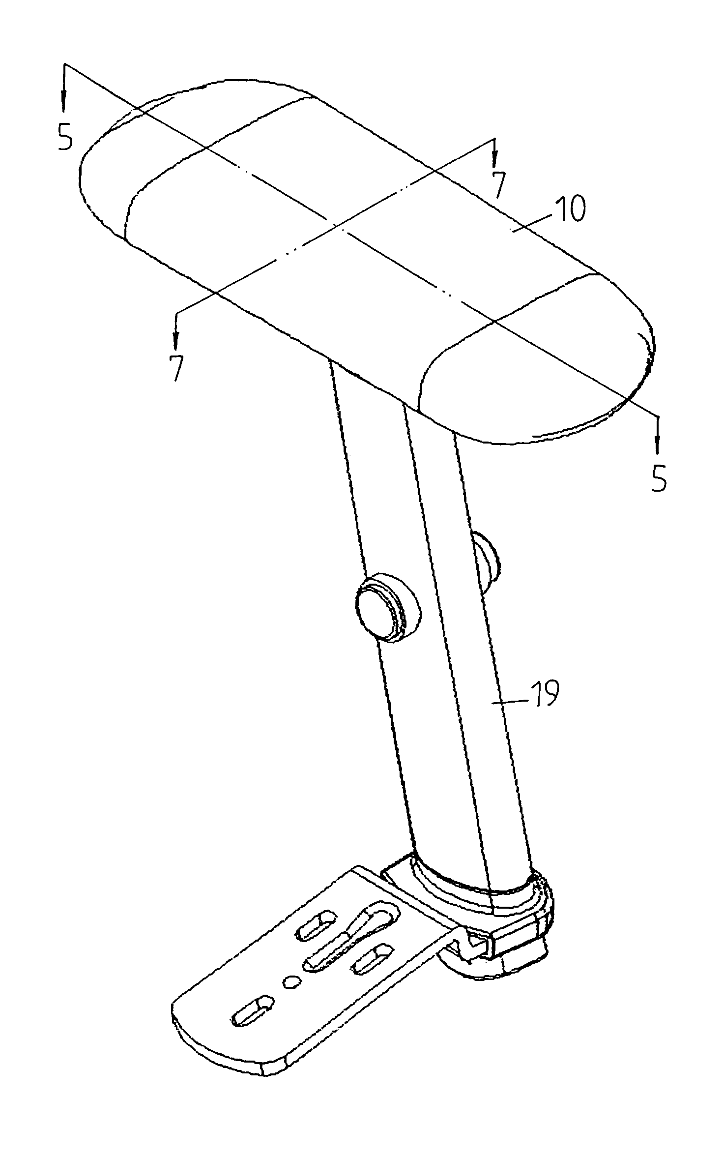
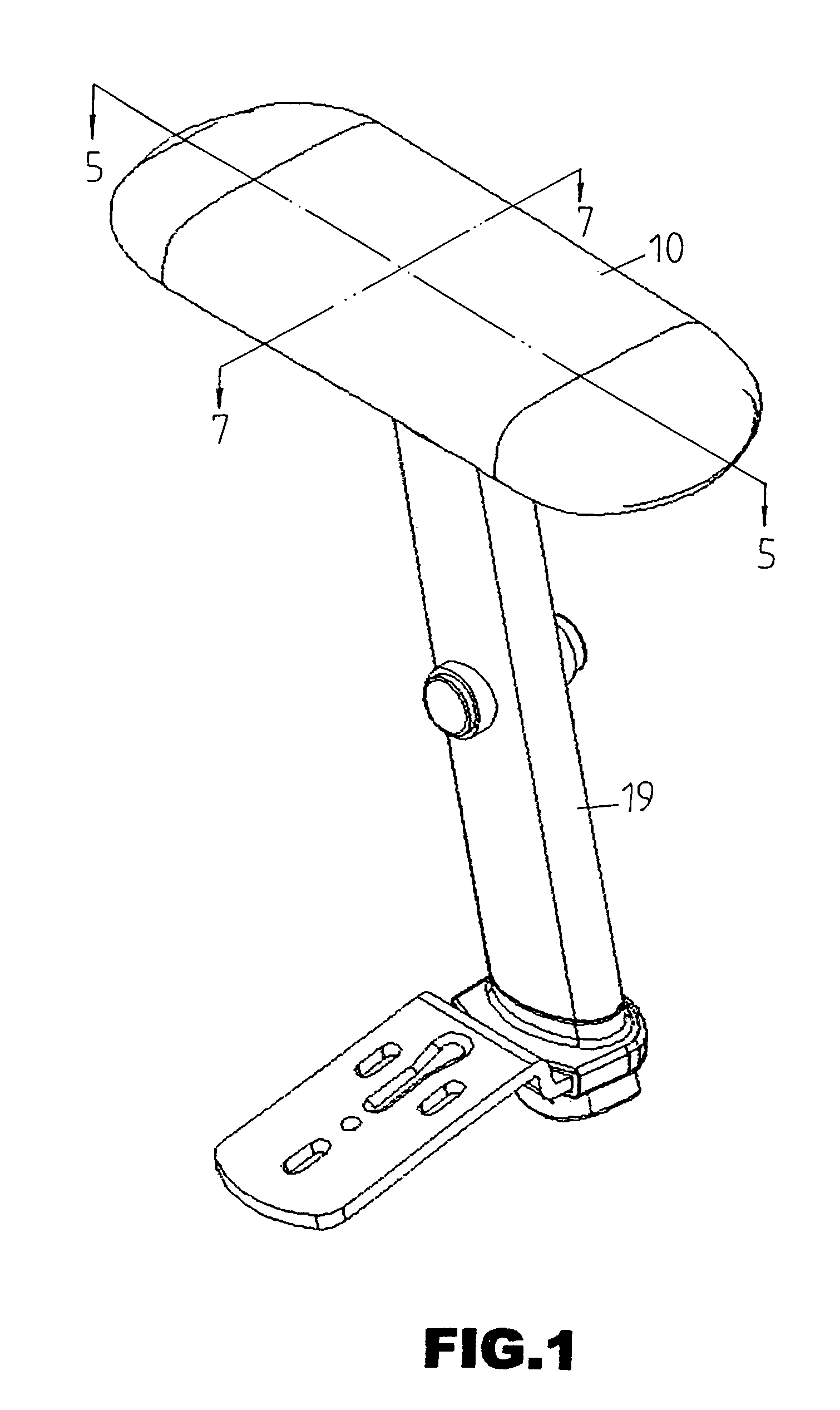
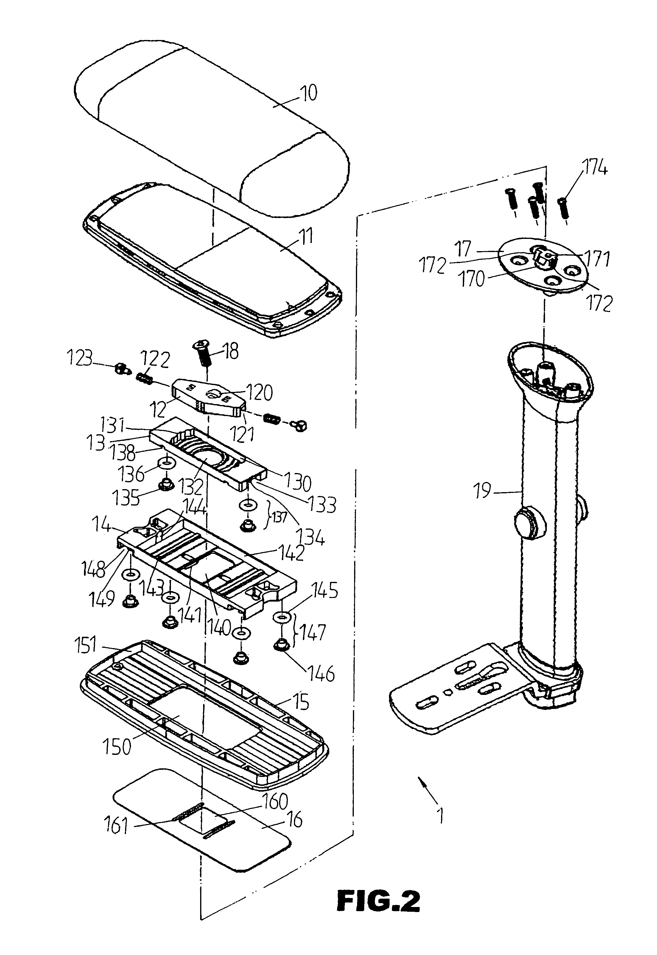
[0025]Referring to the drawings and initially to FIGS. 1-7, an armrest assembly 1 in accordance with the preferred embodiment of the present invention comprises an armrest support 19, a slide seat16 mounted on the armrest support 19, a first slide 15 mounted on the slide seat 16, a second slide 14 mounted on the first slide 15, a rotation member 13 mounted on the second slide 14, a retainer 12 mounted on the rotation member 13, a mounting member 17 secured in the armrest support 19 by bolts 174 and provided with a stud 170 extended through the first slide 15, the second slide 14 and the rotation member 13 and secured to the retainer 12, an armrest 10 mounted on the first slide 15 to encompass the retainer 12, the rotation member 13 and the second slide 14, and a reinforcement 11 mounted between the armrest 10 and the first slide 15.

[0026]Thus, the first slide 15 is movable relative to the slide seat 16 in an axial direction so that the armrest 10 is movable relative to the armrest s...


PUM


Abstract

An armrest assembly for a chair includes an armrest support, a slide seat mounted on the armrest support, a first slide mounted on the slide seat, a second slide mounted on the first slide, a rotation member mounted on the second slide, a retainer mounted on the rotation member, a mounting member secured in the armrest support and provided with a stud extended through the first slide, the second slide and the rotation member and secured to the retainer, and an armrest mounted on the first slide. Thus, the armrest is movable in the axial direction and the transverse direction and is rotatable horizontally relative to the armrest support, so that the position of the armrest can be adjusted easily and freely according to the user's practical requirement.

Description

BACKGROUND OF THE INVENTION[0001]1. Field of the Invention[0002]The present invention relates to an armrest assembly and, more particularly, to a multifunctional armrest assembly for a chair.[0003]2. Description of the Related Art[0004]A conventional armrest assembly for a chair in accordance with the prior art shown in FIG. 11 comprises a track 31 mounted on the bottom of a seat 3 and having a bottom formed with an elongated guide slot 310, and two armrests 2 each having a bent lower end slidably mounted in the track 31 and releasably locked by a rotation knob 4 which is slidable in the guide slot 310 of the track 31 and screwed into the respective armrest 2. Thus, each of the armrests 2 is locked on the track 31 by screwing the respective rotation knob 4 and unlocked from and movable in the track 31 by unscrewing the respective rotation knob 4. Thus, each of the two armrests 2 is movable rightward and leftward relative to the seat 3 to adjust the distance between the armrests 2 so...

Claims


Application Information

Patent Timeline
Patent Type & Authority Patents(United States)
IPC IPC(8): A47C7/54B60N2/75
CPCA47C7/54A47C1/03A47C1/0308A47C1/0307
Inventor TSAI, PO-CHUAN
Owner TSAI PO CHUAN
Why Eureka
Try Eureka