Lighting device

a technology of lighting device and light source, which is applied in the direction of lighting support device, electric lighting with batteries, lighting and heating apparatus, etc., can solve the problems of monotonous lighting effect and uninteresting, and achieve the effect of beautiful lighting

Inactive Publication Date: 2009-07-14
WONG WAI KAI +2
View PDF10 Cites 43 Cited by
  • Summary
  • Abstract
  • Description
  • Claims
  • Application Information

AI Technical Summary

Benefits of technology

[0003]In order to solve the above defects, the purpose of this invention is to provide a lighting device, wherein the position of the lighting unit can be changed in a certain area around one predetermined position; the further purpose of this invention is to provide a lighting unit, besides the function of that its position can be changed in a certain area around one predetermined position, it can also flash in a predetermined sequence after interruption of power source is resumed, so to make the lighting unit to generate more lighting effect and to increase its attraction.
[0009]The mentioned mechanism which oscillates the lighting unit includes an swinging device 10, when the swinging device 10 is given a force and swings, the trigger 2 will work and so as to make the lighting unit lightening meanwhile oscillating along the oscillating shaft 9. The mentioned mechanism which rolls the lighting unit includes a lighting unit 3; it is made to be a round shaped or round-liked shaped structure 11; when this structure 11 is given a force, the mentioned trigger 2 will works so as to make the lighting unit 3 lightening and rolling; thus it can get more beautiful lighting effect than those lighting device whose lighting unit is fixed. By adjusting the shape or position or the lightening and flashing frequency of the lighting unit, it can generate more beautiful lightening effect shaped as real line-single color or colorful concentric circle, pitch arc, broken line or colorful concentric circle, pitch arc and so forth.

Problems solved by technology

However, because the lighting unit is set in a settled position and cannot move, the existing lighting device only can emit the lighting effect at one certain position, it may lead the lighting effect to be very monotone and uninteresting.

Method used


Image

  • Lighting device
  • Lighting device
  • Lighting device

Examples


embodiment 1

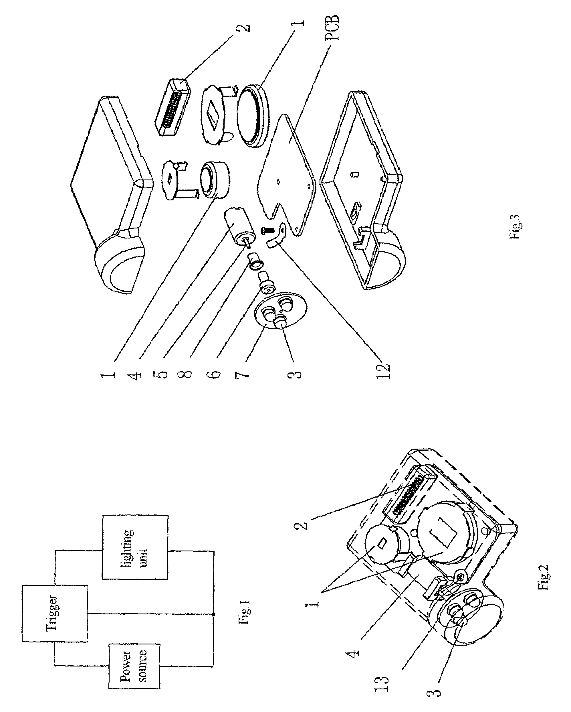
[0027]As shown in FIG. 6, the mentioned lighting circuit device includes a power source 1, a trigger 2, and a lighting unit 3; wherein the power source 1 supplies power to the lighting unit 3 via the trigger 2; and it also includes a motor 4 which is connected in parallel to the mentioned lighting unit 3.

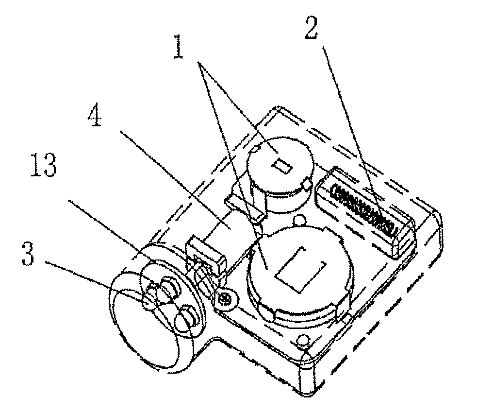
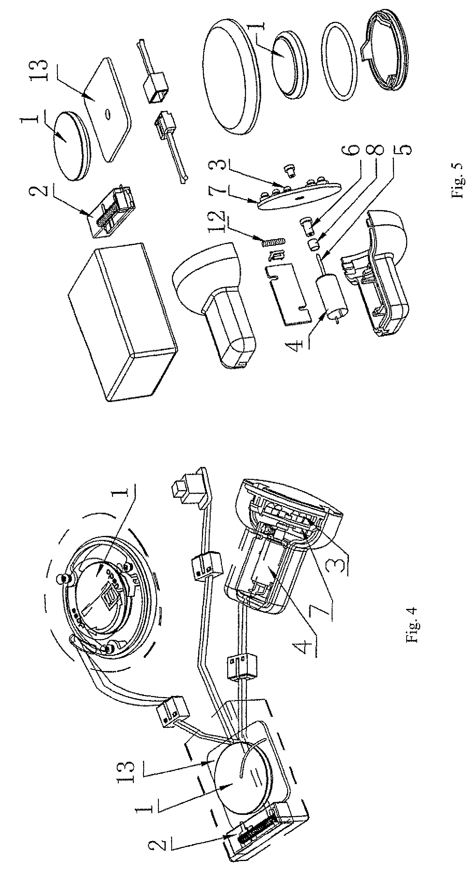
[0028]FIG. 2 is the stereoscopic view of this Embodiment; FIG. 3 is the exploded view of this Embodiment. As shown in these figures, a PCB is installed on the bottom shell of the lighting device of this invention. The connection relationship between the power source 1, the trigger 2 and the lighting unit 3 is shown in FIG. 6; in the circuit, the motor 4 is connected in parallel to the lighting unit 3. A connecting shaft 6 is installed on the transmission shaft 5 of the motor 4 which is supplied by the power source 1; the connecting shaft 6 is connected to a rotating tray 7 on which the lighting unit 3 is installed, the connecting shaft 6 is ringed by a metal ring 8. Once the metal r...

embodiment 2

[0042]FIG. 14. is the stereoscopic view of this Embodiment 2 of this invention. As shown in this fig, there is an swinging device 10 and an oscillating shaft 9. The mentioned swinging device 10 includes a power source 1, a trigger 2 and a lighting unit 3, wherein the power source 1 supplies the lighting unit 3 via the trigger 2. When the swinging device 10 is given a force and oscillates, the trigger 2 will work and so as to make the lighting unit lightening meanwhile oscillating along the oscillating shaft 9; thus it can get more beautiful lighting effect than those lighting device whose lighting unit is fixed. By adjusting the shape or position or the lightening and flashing frequency of the lighting unit, it can generate more beautiful lightening effect shaped as real line-single color or colorful concentric circle, pitch arc, broken line or colorful concentric circle, pitch arc and so forth.

embodiment 3

[0043]FIG. 15. is the stereoscopic view of this Embodiment 3 of this invention. The rotating mechanism includes a power source 1, a trigger 2 and a lighting unit 3. The power source 1, the trigger 2 and the lighting unit 3 are integrated together to be a round shaped or round-liked shaped structure 11. When this structure 11 is given a force, the mentioned trigger 2 will work so as to make the lighting unit 3 lightening and rolling; thus it can get more beautiful lighting effect than those lighting device whose lighting unit is fixed. By adjusting the shape or position or the lightening and flashing frequency of the lighting unit, it can generate more beautiful lightening effect shaped as real line-single color or colorful concentric circle, pitch arc, broken line or colorful concentric circle, pitch arc and so forth.


PUM


Abstract

A lighting device provides with a mechanism which rotates, oscillates or rolls a lighting unit, and includes a power source (1), a trigger (2), a lighting unit (3) and a motor (4), wherein the power source (1) supplies power to the lighting unit (3) and the motor (4) via the trigger (2). The lighting device further includes a control unit which is connected in parallel to the lighting device. By changing internal circuits of the control unit, a pins which connects to an energy storage element is set, therefore the lighting unit flashes in a predetermined sequence after interruption of power is resumed, and the lighting unit moves in a certain track, occurring a path in which position of light spots changed.

Description

RELATED APPLICATIONS[0001]This invention relates to a kind of lighting device and particularly to a lighting device which makes the lighting unit to generate a mechanism whose physical location is alterable.BACKGROUND OF THE INVENTION[0002]Lighting devices are usually fixed on goods such as footwear and clothing to bring a decoration effect; moreover, at night, the flashing can remind the drivers to notice the pedestrian who wears a lighting device, so as to ensure these pedestrians in safety. The existing lighting device, as shown in FIG. 1, comprising a power source, a trigger and a lighting unit; the power source supplies power to the lighting unit via the trigger. By controlling the trigger, it can make the mentioned lighting unit lightening in a prearranged mode. However, because the lighting unit is set in a settled position and cannot move, the existing lighting device only can emit the lighting effect at one certain position, it may lead the lighting effect to be very monoto...

Claims


Application Information

Patent Timeline
Patent Type & Authority Patents(United States)
IPC IPC(8): F21V21/30
CPCF21S10/06
Inventor WONG, WAI KAICHOW, KWOK YINGWONG, KUI HANG
Owner WONG WAI KAI
Why Eureka
Try Eureka