
Generalized presbyopic correction methodology

a presbyopic correction and generalized technology, applied in the field of ophthalmic lenses, can solve the problems of limiting the effectiveness of objective tests, affecting the visual acuity of patients, and the inability of the eye to focus on nearby objects, so as to achieve the effect of improving visual acuity

Active Publication Date: 2009-07-21
ALCON INC
View PDF18 Cites 23 Cited by
  • Summary
  • Abstract
  • Description
  • Claims
  • Application Information

AI Technical Summary

Benefits of technology

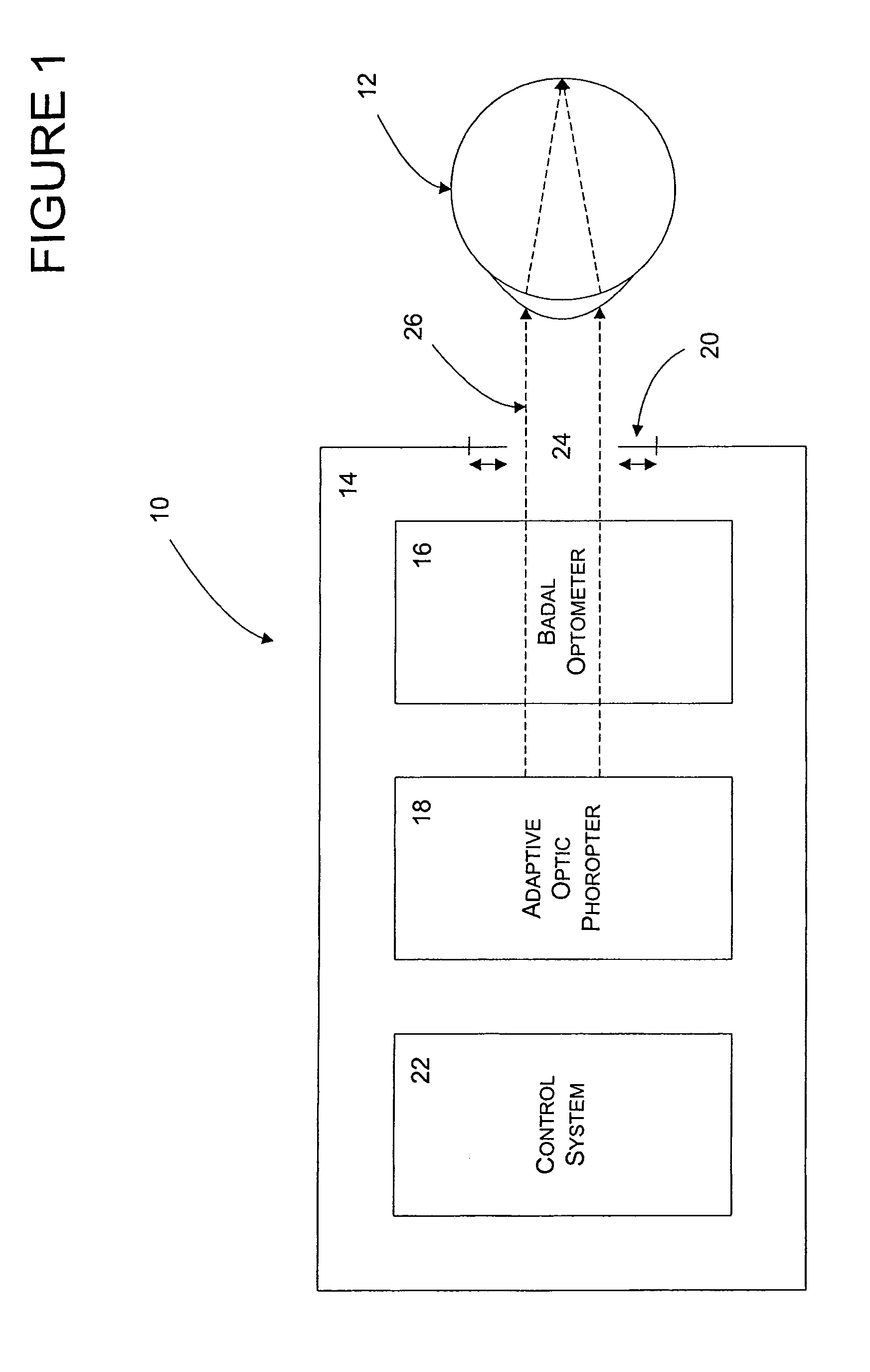
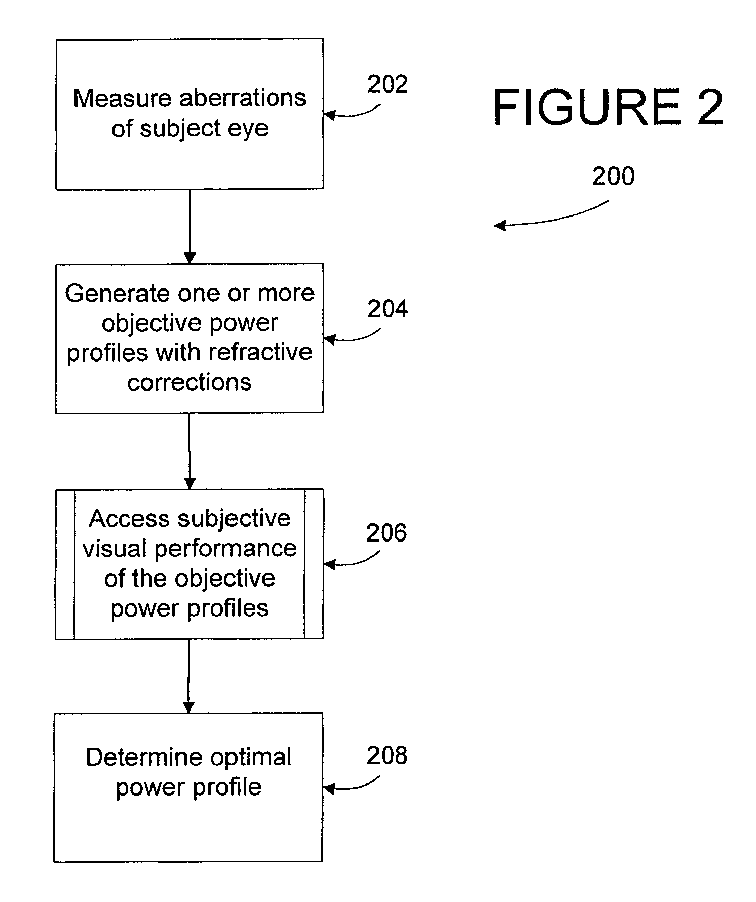
The present invention provides a system and method for determining an optimal power profile for an eye by measuring aberrations of the eye and generating a plurality of power profiles that blur the focusing target equivalently to an ophthalmic lens with corrections for the aberrations and a presbyopic power zone. The system includes an adjustable vergence component and an adaptive optics phoropter, and the method involves iteratively adjusting the vergence and the adaptive optics phoropter until the optimal power profile is determined. The optimal power profile can then be used to fabricate an ophthalmic lens that can improve visual acuity. The invention also provides a complex refractive surface that can be used to fabricate the lens.

Problems solved by technology

Current opinion holds that presbyopia occurs as a person ages when the lens of eye begins to crystallize and lose its elasticity, eventually resulting in the eye losing the ability to focus on nearby objects.
Because vision is subjective, differences in an eye's aberration, the individual's neural processing, and the individual's visual requirements may limit the effectiveness of objective tests.
In addition, even if the technology were currently available to accurately determine an ideal vision correction on a customized basis, the technology is not currently available to fabricate, in a practical way, an ophthalmic lens having a refractive surface with the correction that is stable and registered to an eye's line of sight.

Method used


Image

  • Generalized presbyopic correction methodology
  • Generalized presbyopic correction methodology
  • Generalized presbyopic correction methodology

Examples


Embodiment Construction

[0029]The present invention may be understood more readily by reference to the following detailed description of the invention taken in connection with the accompanying drawing figures, which form a part of this disclosure. It is to be understood that this invention is not limited to the specific devices, methods, conditions or parameters described and / or shown herein, and that the terminology used herein is for the purpose of describing particular embodiments by way of example only and is not intended to be limiting of the claimed invention. Also, as used in the specification including the appended claims, the singular forms “a,”“an,” and “the” include the plural, and reference to a particular numerical value includes at least that particular value, unless the context clearly dictates otherwise. Ranges may be expressed herein as from “about” or “approximately” one particular value and / or to “about” or “approximately” another particular value. When such a range is expressed, another...


PUM


Abstract

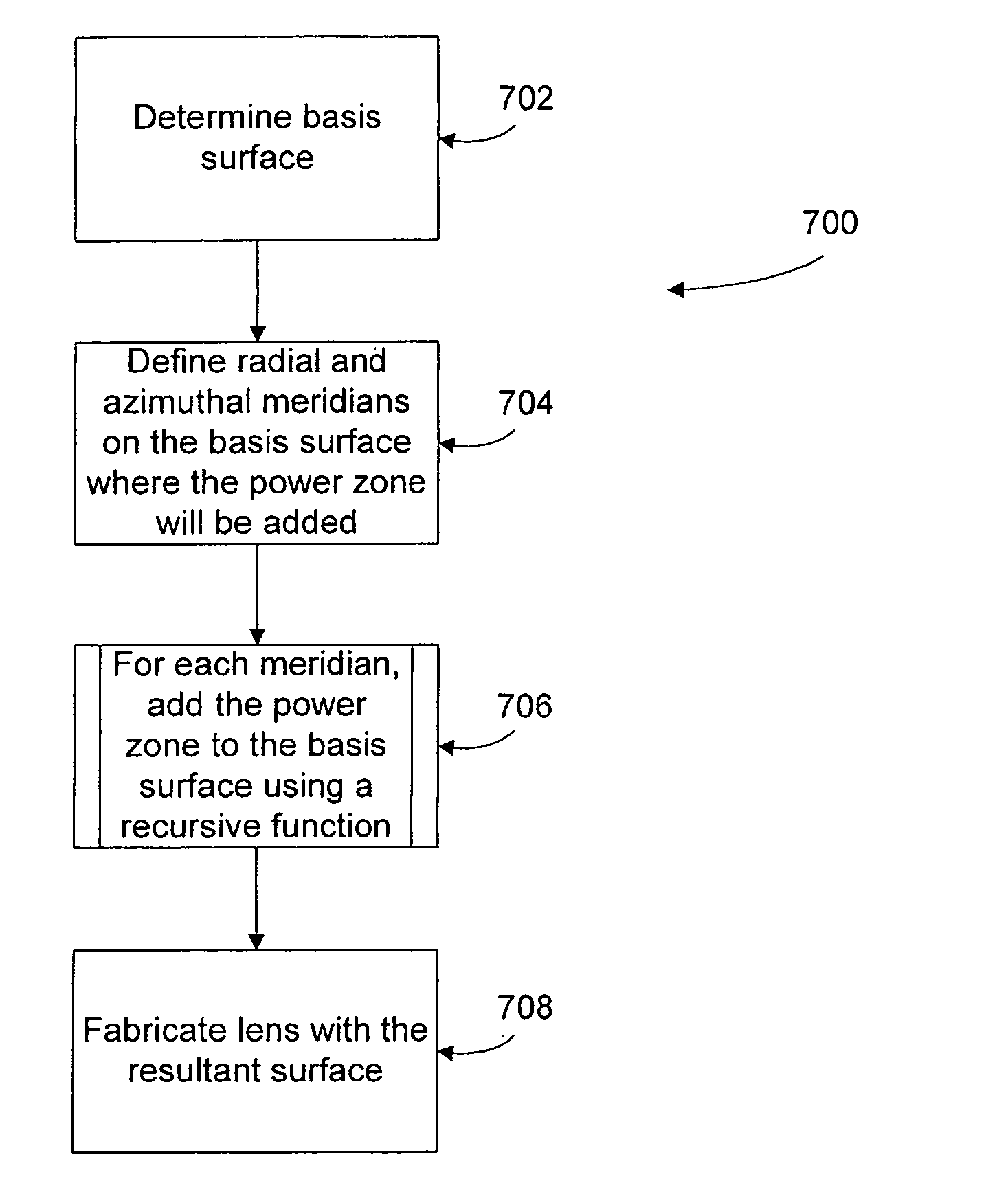
An adaptive optics phoropter is aligned with a Badal optometer and an adjustable aperture component to subjectively determine an optimal vision correction as a power profile for an ophthalmic lens or ablating a cornea. The optimal power profile is preferably determined in an iterative process by adjusting the vergence of the Badal optometer and aperture size of the adjustable aperture component for power profiles with presbyopic power zones having different amplitudes, shapes, widths, and / or de-centering. Also included is a method of recursively computing a refractive surface with a regular presbyopic power zone (e.g., according to the optimal power profile) and adding it onto an underlying irregular Zernike-basis-set aberration-corrected surface in a linear fashion for fabricating an ophthalmic lens.

Description

CROSS-REFERENCE TO RELATED APPLICATION[0001]This application claims the benefits under 35 USC 119(e) of the U.S. Provisional Patent Application No. 60 / 882,950 filed Dec. 31, 2006 herein incorporated by reference in its entirety.TECHNICAL FIELD[0002]The present invention relates generally to the field of ophthalmic lenses and, more particularly, to using adaptive optics to subjectively adapt a subject's vision almost simultaneously to produce optimally corrected vision with an optimal power profile, and recursively determining a correction surface based on the optimal power profile for fabricating a lens.BACKGROUND OF THE INVENTION[0003]Contact lenses are widely used for correcting many different types of vision deficiencies. These include defects such as near-sightedness and far-sightedness (myopia and hypermetropia, respectively), astigmatism vision errors, and defects in near range vision usually associated with aging (presbyopia). Current opinion holds that presbyopia occurs as a...

Claims


Application Information

Patent Timeline
Patent Type & Authority Patents(United States)
IPC IPC(8): A61B3/00G02C7/02
CPCA61B3/103A61B3/028
Inventor LINDACHER, JOSEPH M.ANDINO, RAFAEL V.ROBIRDS, SCOTT R.DECENZO-VERBETEN, TERESA
Owner ALCON INC
Learn More